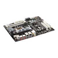
JP1 2-pin DRAM Voltage
(VCC)
2.5V (DDR): Open Pins 1-2
3V (SDR): Short Pins 1-2
JP1
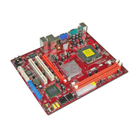
J2A/B/C/D
J3A/B/C/D
20-pin DDR/SDR
DRAM Type
Selector
DDR1, DDR2:
Short all J2A/B/C/D and
J3A/B/C/D pins
DIMM1, DIMM2:
Open all J2A/B/C/D and
J3A/B/C/D pins
J2A/B/C/D
J3A/B/C/D
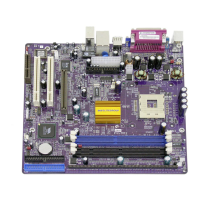
JP2 3-pin Keyboard
Power On
5V: Short Pins 1-2
5VSB: Short Pins 2-3
JP2
1
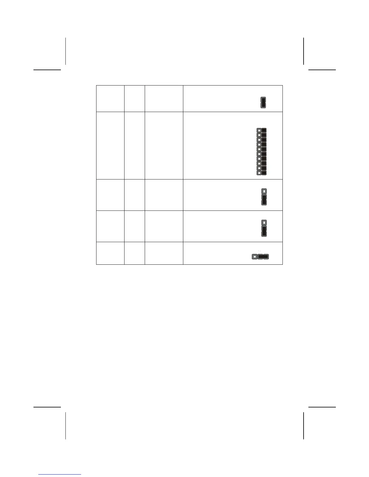
J13 3-pin Flash ROM
Voltage (VCC)
5V: Short Pins 1-2
3V: Short Pins 2-3
J13
1
JP4 3-pin Flash ROM
Size
2M: Short Pins 1-2
4M: Short Pins 2-3
JP4
1
JBAT1
This jumper is to clear the contents of CMOS memory. You may need to clear
the CMOS memory if the settings in the Setup Utility are incorrect that pre-
vents your mainboard from operating. To clear the CMOS memory, disconnect
all the power cables from the mainboard and then move the jumper cap into
the CLEAR setting for a few seconds. This jumper enables you to reset BIOS.
JP1A1/ JP1B1
This jumper enables you to select the CPU frequency. Both jumpers should
be set concurrently.
JP1: DRAM Voltage (VCC)
This jumper enables to select voltage of DRAM.
J2A/B/C/D, J3A/B/C/D: DDR/SDR DRAM Type Selector
This jumper enables to select the type of DDR or SDR DRAM.
10
 Loading...