JP2: Keyboard Power On
This jumper enables any keyboard activity to power up a system previously in
a standby or sleep state.
J13: Flash ROM Voltage (VCC)
This jumper enables to select voltage of flash ROM.
JP4: Flash ROM Size
This jumper enables to select size of flash ROM.
C
C
o
o
n
n
n
n
e
e
c
c
t
t
i
i
n
n
g
g
C
C
a
a
s
s
e
e
C
C
o
o
m
m
p
p
o
o
n
n
e
e
n
n
t
t
s
s
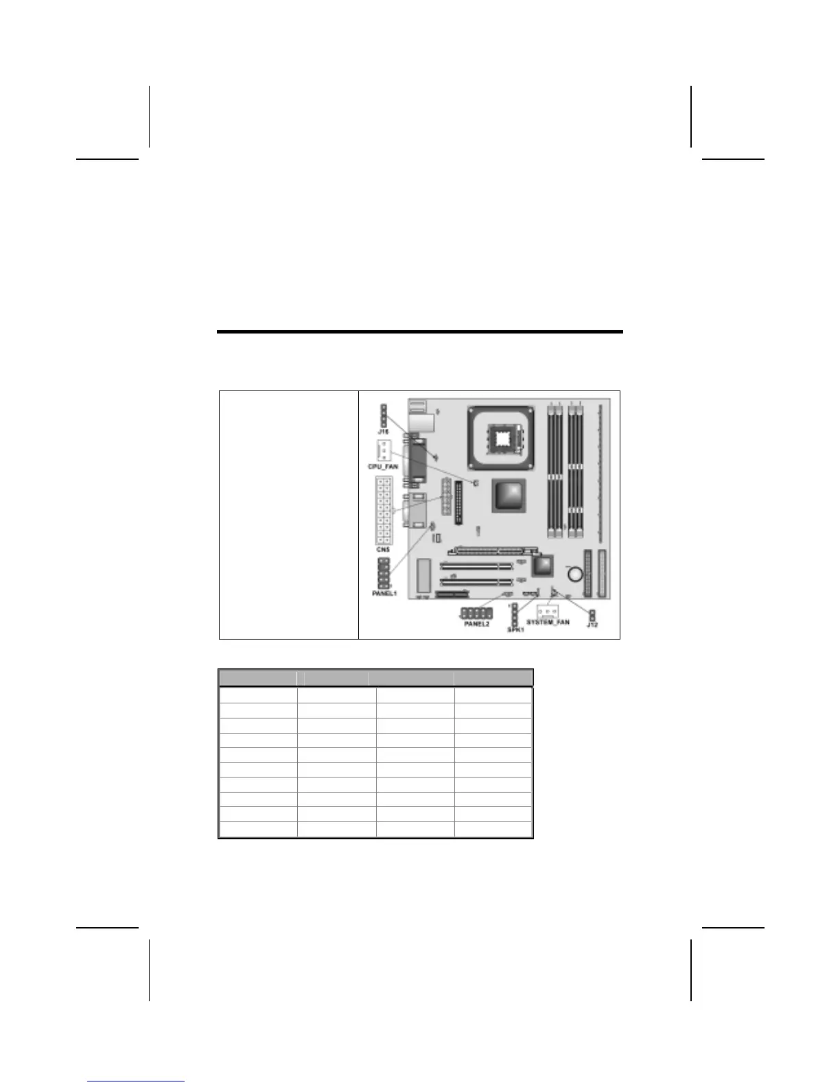
After you have installed the mainboard into a case, you can begin connecting
the mainboard components. Refer to the following:
1. Connect the case
power supply
connector to CN5.
2. Connect the CPU
cooling fan cable to
CPU_FAN.
3. Connect the case
cooling fan connector
to SYSTEM_FAN.
4. Connect the case
speaker cable to
SPEAKER1.
5. Connect the case
switches and indicator
to PANEL1/
PANEL2.
CN5: ATX 20-pin Power Connector
Pin Signal Name Pin Signal Name
1 +3.3V 11 +3.3V
2 +3.3V 12 -12V
3 Ground 13 Ground
4 +5V 14 PS ON#
5 Ground 15 Ground
6 +5V 16 Ground
7 Ground 17 Ground
8 PWRGD 18 +5V
9 +5VSB 19 +5V
10 +12V 20 +5V
11
 Loading...