EasyManua.ls Logo

ECS P17G/1333 Series User Manual

ECS P17G/1333 Series
41 pages
To Next Page IconTo Next Page
Page #1 background imageLoading...
Page #1 background image
i
Motherboard User’s Guide
This publication, including photographs, illustrations and software, is under the
protection of international copyright laws, with all rights reserved. Neither this
users guide, nor any of the material contained herein, may be reproduced without
the express written consent of the manufacturer.
The information in this document is subject to change without notice. The manu-
facturer makes no representations or warranties with respect to the contents hereof
and specifically disclaims any implied warranties of merchantability or fitness for
any particular purpose. Further, the manufacturer reserves the right to revise this
publication and to make changes from time to time in the content hereof without
obligation of the manufacturer to notify any person of such revision or changes.
Trademarks
IBM, VGA, and PS/2 are registered trademarks of International Business Ma-
chines.
Intel, Pentium/II/III, Pentium 4, Celeron and MMX are registered trademarks of
Intel Corporation.
Microsoft, MS-DOS and Windows 98/ME/NT/2000/XP are registered trademarks
of Microsoft Corporation.
AMI is a trademark of American Megatrends Inc.
It has been acknowledged that other brands or product names in this manual are
trademarks or the properties of their respective owners.
Static Electricity Precautions
1. Don’t take this motherboard and components out of their original static-
proof package until you are ready to install them.
2. While installing, please wear a grounded wrist strap if possible. If you
don’t have a wrist strap, discharge static electricity by touching the bare
metal of the system chassis.
3. Carefully hold this motherboard by its edges. Do not touch those compo-
nents unless it is absolutely necessary. Put this motherboard on the top of
static-protection package with component side facing up while installing.
Pre-Installation Inspection
1. Inspect this motherboard whether there are any damages to components
and connectors on the board.
2. If you suspect this motherboard has been damaged, do not connect power
to the system. Contact your motherboard vendor about those damages.
Copyright © 2007
All Rights Reserved
P17G/1333 Series, V1.0A
August 2007
Question and Answer IconNeed help?

Do you have a question about the ECS P17G/1333 Series and is the answer not in the manual?

ECS P17G/1333 Series Specifications

General IconGeneral
BrandECS
ModelP17G/1333 Series
CategoryMotherboard
LanguageEnglish

Summary

Trademarks

Static Electricity Precautions

Pre-Installation Inspection

Chapter 1 Introduction

Key Features

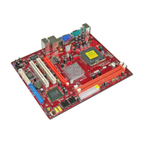
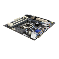
The key features of this motherboard include:

Chipset

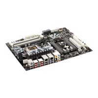
There are 945GC Northbridge and Intel I/O Controller Hub 7 (ICH7)...

Onboard I/O Ports

Onboard LAN (optional)

BIOS Firmware

Chapter 2 Motherboard Installation

Motherboard Components

I/O Ports

Installing the Processor

Fail-Safe Procedures for Over-clocking

When end-users encounter failure after attempting over-clocking...

CPU Installation Procedure

Follow these instructions to install the CPU:

Installing Memory Modules

Memory Module Installation Procedure

Jumper Settings

CLR_CMOS: Clear CMOS Jumper

Use this jumper to clear the contents of the CMOS memory...

USBPWR_F/USBPWR_R: USB Power Select Jumper

Use these jumpers to select the voltage for USB port.

Install the Motherboard

Connecting Optional Devices

F_AUDIO1: Front Panel Audio Header

This header allows the user to install auxiliary front-oriented microphone and line-out ports...

F_USB1/F_USB2: Front Panel USB Headers

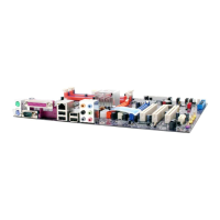
The motherboard has USB ports installed on the rear edge I/O port array...

Install Other Devices

Floppy Disk Drive

The motherboard ships with a floppy disk drive cable...

IDE Devices

IDE devices include hard disk drives, high-density diskette drives...

Serial ATA Devices

The Serial ATA (Advanced Technology Attachment) is the standard interface...

Expansion Slots

PCIEX16 Slot

The PCIEX16 is used to install an external PCI Express graphics card...

PCI 1~2 Slots

This motherboard is equipped with two standard PCI slots. PCI stands for...

Chapter 3 BIOS Setup Utility

Introduction

The BIOS Setup Utility records settings and information of your computer...

Running the Setup Utility

Every time you start your computer, a message appears on the screen...

Standard CMOS Setup Page

Processor

The item is automatically detected by the system at start up time...

System Memory

The item is automatically detected by the system at start up time...

Time and Date

The Date and Time items show the current date and time on the computer...

Advanced Setup

CPU TM function (Enabled)

For some specific brands of CPU, you can use this item to control the CPU frequency...

Max CPUID Value Limit (Disabled)

Use this item to enable or disable the Max CPU ID value limit...

Execute Disable Bit (Disabled)

This item is a security feature that helps you protect your CPU...

Intel (R) SpeedStep (tm) tech. (Disabled)

This item allows users to enable or disable the EIST...

Enhanced Halt (C1E) (Enabled)

This item enables or disables enhanced halt.

Quick Power on Self Test (Enabled)

Enable this item to shorten the power on testing (POST)...

Boot Up Numlock Status (On)

This item defines if the keyboard Num Lock key is active when your system is started.

Advanced Chipset Setup

Configure DRAM Timing (By SPD)

When this item is set to enable, the DDR timing is configured using SPD...

DVMT Mode Select (DVMT Mode)

This item allows you to select the DVMT operating mode.

DVMT/Fixed Memory (128MB)

When set to Fixed Mode, the graphics driver will reserve a fixed portion of the system memory...

Integrated Peripherals

Onboard IDE Controller (Enabled)

Use this item to enable or disable the onboard IDE interface.

Onboard SATA Controller (Enabled)

Use this item to enable or disable the onboard SATA controller.

USB Functions (Enabled)

Use this item to enable or disable the USB function.

Legacy USB Support (Enabled)

Use this item to enable or disable support for legacy USB devices...

Audio Controller (Enabled)

Use this item to enable or disable the onboard audio controller.

OnBoard LAN Function (Enabled)

Use this item to enable or disable the onboard LAN function.

OnBoard LAN Boot ROM (Disabled)

Use this item to enable or disable the booting from the onboard LAN...

Power Management Setup

*ACPI Suspend Mode (S3(STR))

Use this item to define how your system suspends...

Soft-Off By PWR-BTTN (Delay 4 Sec)

Under ACPI (Advanced Configuration and Power management Interface) you can create...

PC Health Status

Shutdown Temperature (Disabled)

Enable you to set the maximum temperature the system can reach before powering down.

Smart Fan Function

Scroll to this item and press <Enter> to view the following screen:

Frequency/Voltage Control

Manufacturer (Intel)

This item displays the information of current manufacturer of the CPU installed in your computer.

CPU Frequency Setting (266MHz)

This item allows you to set CPU frequency. And the CPU frequency will be...

DRAM Frequency (Auto)

This item shows the frequency of the DRAM in your computer. When it is FSB...

Auto Detect DIMM/PCI Clk (Enabled)

When this item is enabled, BIOS will disable the clock signal of free DIMM/PCI slots.

Spread Spectrum (Disabled)

If you enable spread spectrum, it can significantly reduce the EMI...

CPU Frequency (Auto)

Use this option to adjust CPU frequency. And this item shows only when...

Load Optimal Defaults

Supervisor Password

User Password

Save & Exit Setup

Exit Without Saving

Chapter 4 Software & Applications

Introduction

This chapter describes the contents of the support CD-ROM that comes with the motherboard package.

Installing Support Software

Insert the support CD-ROM disc in the CD-ROM drive. When you insert the CD-ROM disc...

Hyper-Threading CPU

Related product manuals