24
Installing the Motherboard
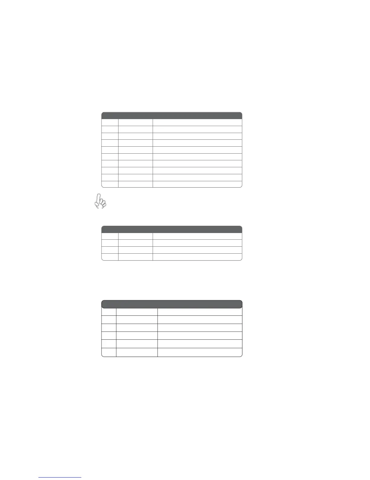
AUDIO1: Front Panel Audio header
This header allows the user to install auxiliary front-oriented microphone and line-out ports
for easier access.
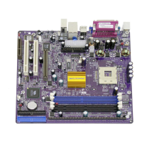
JCDIN1: CD Audio Input header
If your front panel cable is seperated, please connect it to pin1 and pin3 or
pin5 and pin7 to activate the MIC function.
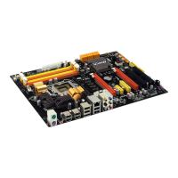
IR1: Infrared port
The mainboard supports an Infrared (IR1) data port. Infrared ports allow the wireless
exchange of information between your computer and similarly equipped devices such as
printers, laptops, Personal Digital Assistants (PDAs), and other computers.
Pin Signal Name Function
1 AUD_MIC Front Panel Microphone input signal
2 AUD_GND Ground used by Analog Audio Circuits
3 AUD_MIC_BIAS Microphone Power
4 AUD_VCC Filtered +5V used by Analog Audio Circuits
5 AUD_F_R Right Channel audio signal to Front Panel
6 AUD_RET_R Right Channel Audio signal to Return from Front Panel
7 REVD Reserved
8 Key No Pin
9 AUD_F_L Left Channel Audio signal to Front Panel
10 AUD_RET_L Left Channel Audio signal to Return from Front Panel
Pin Signal Name Function
1 CD in_L CD In left channel
2 GND Ground
3 GND Ground
4 CD in_R CD In right channel
Pin Signal Name Function
1 Not Assigned Not assigned
2 Key No pin
3 +5V IR Power
4 GND Ground
5 IRTX IrDA serial output
6 IRTX IrDA serial input