5
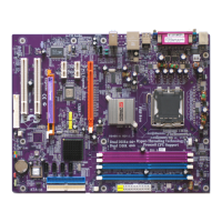
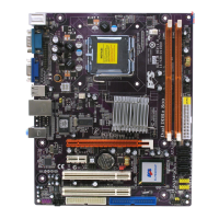
Introducing the Motherboard
Table of Motherboard Components
This concludes Chapter 1. The next chapter explains how to install the motherboard.
Users please note that DDR & DDR2 can’t both be applied at the same time on
this motherboard. Users can use either DDR or DDR2 memory modules only!
1 CPU Socket LGA775 socket for Pentium 4/Celeron CPU
2 CPU_FAN CPU cooling fan connector
5 ATX_POWER Standard 24-pin ATX power connector
LABEL COMPONENT
7 IDE1 Primary IDE channel
3 DIMM1~2 240-pin DDR2 SDRAM slots
4 DIMM3~4 184-pin DDR SDRAM slots
12 SATA1~4 Serial ATA connectors
11 CLR_CMOS Clear CMOS jumper
13 PANEL1 Front panel switch/LED header
9 BIOS_WP BIOS protection jumper
8 IDE2 Secondary IDE channel
10 SPK1 Speaker header
6 PWR_FAN Power fan connector
15 FDD Floppy diskette drive connector
19 IR1 Infrared header
14 SYS_FAN System cooling fan connector
27 ATX12V 4-pin +12V power connector
22 PCIEX16 PCI Express x16 graphics card slot
21 USB3-4 Front Panel USB headers
24 CD_IN Analog audio input connector
25 AUDIO1 Front panel audio header
18 AGP AGP Express slot
17 SPDIFO1 SPDIF out header
20 PCIE1~2 PCI Express x1 slots
23 AUX_IN* Auxliary-in header
26 TV_OUT* TV-out header
16 PCI1~2 32-bit add-on card slots
“*” stands for optional components and may not exist onboard.