MT-206/MT-207 Trolley Installation Guide
- 6 -
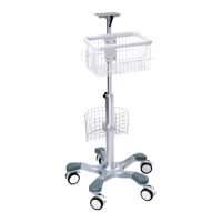
5 The top splint and link board are
assembled together in package. Pull
downwards the pin on the top splint, hold
to slide them apart.
6 Loosen two screws on the top splint to take
off the rotary axis, then pull the rotary axis
through the flange hole of lifter rod.
Insert the L-shape angle adjustment handle
and a G screw into the two holes of flange,
but do not tighten them.
NOTE:
Put the L-shape angle adjustment
handle at the thinner side, while the G
screw on the other side.
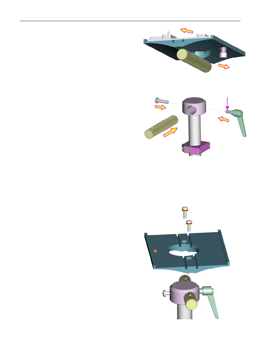
7 Put the top splint on the flange of lifter
rod. Make sure it faces the hole of
rotary axis, then fix them well with
two screws taken off in step 6.
Tighten the L-shape angle adjustment
handle and the G screw.
ngle adjustment