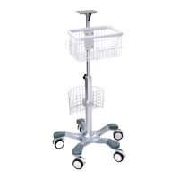
The EDAN MT-206/MT-207 Trolley is a medical equipment accessory designed to provide a mobile and stable platform for various EDAN patient monitors. This installation guide, version 1.3, outlines the assembly procedure, safety warnings, and component details for the trolley.
Function Description:
The primary function of the MT-206/MT-207 Trolley is to facilitate the mobility and positioning of EDAN patient monitors in clinical environments. It allows healthcare professionals to easily transport monitors between different patient rooms, departments, or within the same room, enhancing workflow efficiency and patient care. The trolley is designed to be sturdy and stable, ensuring the safety of the monitor during transport and use. It includes features for adjusting the monitor's angle, providing optimal viewing for clinicians. The trolley also offers storage options, such as a handrail basket and an optional lower basket, for accessories and supplies, keeping essential items within reach.
Important Technical Specifications:
- Model Numbers: MT-206, MT-207
- Maximum Load (Top Splint): 8 kg. This specification is crucial for preventing damage to the trolley and ensuring the safety of the monitor. Overloading the top splint is explicitly warned against.
- Compatibility: The trolley is compatible with a range of EDAN monitors, including M3, M3B, iM9 series, iM8 series, iM50, iM60, iM70, and iM80. Compatibility is achieved through the use of specific link boards tailored to each monitor series.
- Casters: Equipped with 3-inch medical casters, five in total, for smooth and easy movement. These casters include a pedal mechanism for locking the trolley in place and releasing it for movement.
- Materials: The chassis and stand post are constructed from durable materials to withstand the demands of a medical environment. The baskets are made of metal wire for holding accessories.
- Dimensions (Implied from parts): While not explicitly stated, the components suggest a compact design suitable for medical settings, with a stand post for height and an angle adjustment mechanism for the monitor.
- Screws and Fasteners: The assembly requires various screws and washers, including M10×50 bolts, M6×25 spacing bolts, M5×14 cross recessed pan head screws, and different sizes of cross recessed countersunk head screws (M4×25, M4×20, M3×12) depending on the monitor model. Φ12 and Φ10 normal type spring and plain washers are also used. A 17# normal open spanner is provided for assembly.
- Balancing Weight (MT-207 specific): The MT-207 trolley includes a balancing weight installed on the chassis to enhance stability, particularly when supporting heavier monitors or accessories.
Usage Features:
- Mobility: The five 3-inch medical casters allow for effortless movement of the trolley across various floor surfaces in a hospital or clinic.
- Locking Mechanism: Each caster is equipped with a pedal. Stepping on the pedal locks the trolley in position, preventing unintended movement, which is critical for patient safety during monitoring. Pushing the pedal up releases the lock, allowing the trolley to be moved.
- Angle Adjustment: The top splint features an angle adjustment mechanism, allowing the user to tilt the monitor to an optimal viewing angle. This enhances visibility for healthcare professionals, regardless of their height or position relative to the monitor. The L-shape angle adjustment handle and a G screw are used for this purpose.
- Accessory Storage:
- Handrail Basket: A standard feature that provides convenient storage for cables, sensors, or other small accessories, keeping them organized and accessible.
- Lower Basket (Optional): For additional storage needs, an optional lower basket can be installed, providing more space for larger items or supplies. This requires simultaneous use with a basket flange.
- Monitor Mounting: The trolley utilizes a link board system to securely attach different EDAN patient monitors. Specific link boards are designed for M3/M3B series and iM9/iM8 series monitors, ensuring a snug and stable fit.
- Easy Assembly: The installation guide provides clear, step-by-step instructions with illustrations, making the assembly process straightforward for authorized personnel. A crosshead screwdriver and the provided spanner are the main tools required.
- Adjustable Stand Post: The stand post allows for height adjustment, though the specific range is not detailed. Users are cautioned to be careful not to trap their fingers when adjusting the stand post.
Maintenance Features:
- Regular Safety Checks: An overall check of the trolley, including a safety check, must be performed by qualified personnel every 6 months and after any repairs. This ensures the trolley remains in safe operating condition.
- Authorized Service Personnel: Assembling or disassembling the trolley should only be performed by service personnel authorized by the manufacturer. This ensures proper installation and prevents potential damage or safety hazards.
- Secure Fasteners: During assembly, it is emphasized to use a crosshead screwdriver to secure all screws tightly. This prevents loosening over time and maintains the structural integrity of the trolley.
- Caster Functionality Check: Before initial setup, users are advised to ensure that the casters can rotate normally. This simple check helps identify any issues with mobility early on.
- Firm Assembly Verification: Before applying the monitor, it is crucial to ensure that the trolley is firmly assembled and in good condition. This pre-use check is a vital safety measure.
- Disposal Guidelines: At the end of its useful life, the trolley and its accessories must be disposed of according to local regulations. Alternatively, they can be returned to the dealer or manufacturer for recycling or proper disposal, promoting environmental responsibility.
- Spare Parts: The package includes spare screws for various components, facilitating minor repairs or replacements if needed, without requiring immediate reordering of parts. The table specifies the quantity of screws required for installation versus the total quantity provided, indicating the availability of spares.