3-6
=
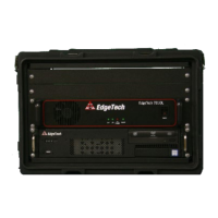
3.2.3 701-DL with Computer Controls, Indicators, and Connections
The 4205-Rack Mount (701-DL and 2U-CPU Combo) controls, indicators, and connections are described
below:
Rocker switch. Turns the 701-DL Link on or off.
LAN Indicator Light
Green indicator. Flashes continuously when an Ethernet connection is
established.
LINK Indicator Light
Green indicator. Flashes while the 701-DL Digital Link is establishing a
reliable communications link with the Towfish. Illuminates continuously
when a reliable communications link with the Towfish is established.
Fish Power Indicator Light
Red Indicator. Illuminated when the 701-DL Digital Link is on, and the tow
vehicle is properly connected to it.
Green indicator. Illuminated when the 701-DL Digital Link is on.
Connection for AC power cord.
Line Power Switch
Rocker switch. Switches AC power to POWER switch on the front panel of
the 701-DL Digital Link.
Data Connector
RJ-45 Standard Ethernet connection for connecting to the external topside
processor.
Sync Connector
It provides an input connection for a TTL external trigger that is sent to the
towfish.
SubConn MCBH4F female connector to sea cable going out to tow vehicle.
USB Connectors
(2) USB connectors. Four on the back panel and two on the front. Located
on CPU.
CEE-type AC input connector. Connects to 100-264 VAC, 50/60 Hz power.
Rocker switch. Turns the 2U-CPU computer on or off.
USB Connectors
(6) USB connectors. Four on the back panel and two on the front. Located
on CPU.
Ethernet Connector
RJ-45 connector. It provides a 10/100BaseT Ethernet connection. Located
on CPU and 701-DL.
Video card
Video card with 4 Mini DP (Display)Connectors. Provides video display to
the monitor.
COM-1 NAV Connector
DB-9 female connector. RS-232 serial port that connects to the navigation
system. Located on CPU.
COM-3 Connector
DB-9 female connector. RS-232 serial port that can be used to connect to
the navigation system. Located on CPU.
Table 3-2: 701 DL With Computer Controls, Indicators and Connections