6
Dimmer and Rack Maintenance
The MX system, like all electrical / electronic equipment
is affected by the presence of dirt and dust. We recom-
mend the rack be opened, the modules removed and all
items cleaned to remove this dust.
Pleases follow this procedure:
•Shutdown and Disconnect Power.
•Remove the door.
•Remove each dimmer module and individually
clean either by vacuum or low pressure com
pressed air.
•Clean the other interior areas of the rack in the
same manner as the individual modules.
•Inspect the internal connections of the main
feeders and of the branches to the module
plugs.
•Inspect the connector ends for discoloration
indicating a poor connection.
•After cleaning and inspection, replace the
modules and the door.
Note: Annual cleaning is recommended, more frequently
if the environment is particularly dirty.
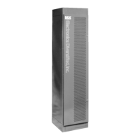
To help prevent the build up of dirt, the Electrostatic Air
Filters may be cleaned or replaced frequently.
To clean the Air filters:
•Remove air filters from door.
• Wash with a light to medium pressure water
spray. Use cold to luke-warm water.
• Allow to dry and replace.
Note: The filter(s) must be replaced with the correct
side facing the interior of the cabinet.
Dimmer Module
The standard dimmer modules provide one LED indicator
per dimmer circuit which gives a visual indication of the
dimmer activity. Also provided is another LED indicator
which warns of a fault in that module.
1. Phase A fuse
2. Phase B fuse
3. Phase C fuse
4. Factory Setting switches ( Normally all on)
5. Memory clear (Normally in the left position, as shown)
6. Battery for memory
7. Processor reset
ROM
mPU
1 2 3 4 5
6 7
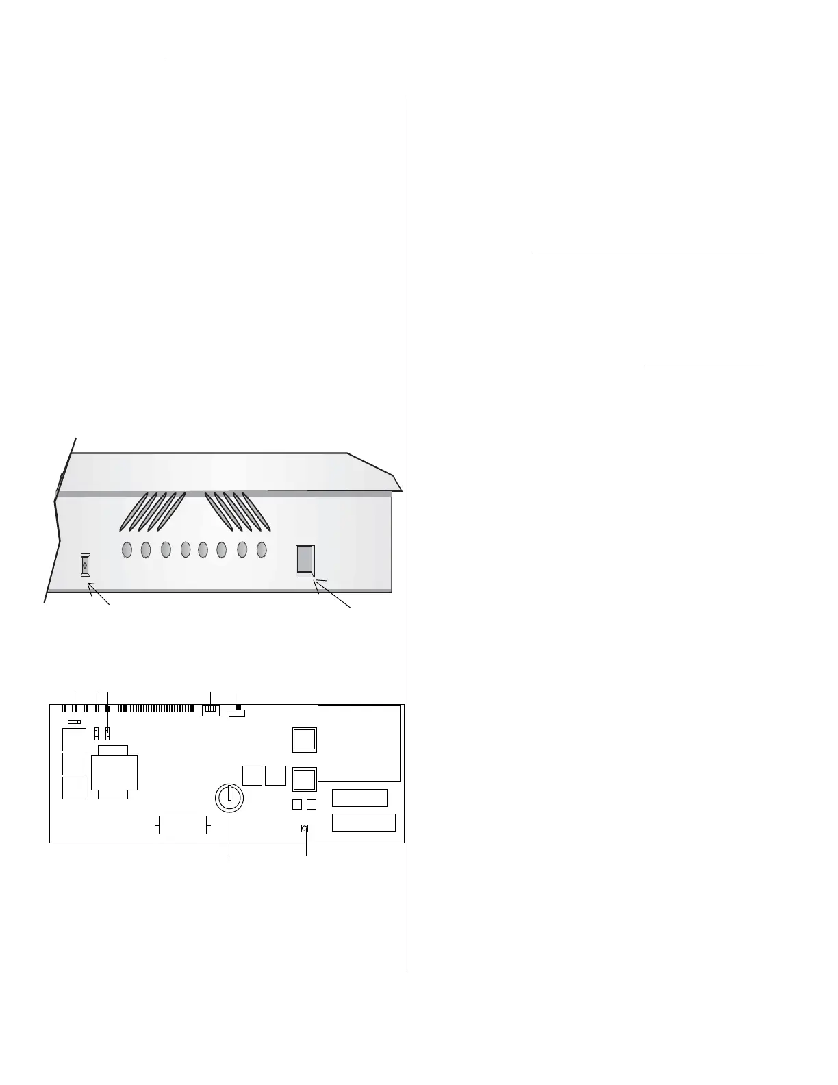
Control module's circuit board
Control Module
The control module is the user interface with the electronic
brain and monitoring features of the MX series dimmer
rack. The illustration shows the location of the DMX input
connection, ( a control cable from a lighting control board
may be plugged here ). Also, to the right is the connection
for the hand-held programmer. Between these are LED
indicators of internal rack functions.
These function indicators are limited to displaying the most
basic presence or absence of the electrical or electronic
signal named on the face of the rack immediately below
each LED.
The only LED that when lighted is an indication of a problem
with the rack, or, more specifically with the dimmer(s) in the
rack, is labeled Fault. All other LEDs are lighted when the
function named is activated under normal operation.
Also in the area of the LEDs is a service switch. This switch
is recessed and requires the aid of a small pointed tool to
activate. This switch allows for all the dimmers to be turned
to full-up. The switch essentially bypasses all other control
signals to the control module.
To set module back to Default Setting:
Power down the rack, if powered, and remove te control
module. Locate the Memory clear switch on the back of the
module. Move the switch to the left hand side ( towards the
Factory Setting switches) and leave for five seconds.
Afterwords, move the switch back to the right, and palce the
moduel back inside the rack. Power up the rack and verify
settings.
DMX 1
DMX 2
Ø A
Ø B
Ø C
Fault
Service
DMX input Programmer port
 Loading...