ENGLISH
36
HYDRAULIC CONNECTIONS
Hydraulic schematic diagram of built in kit.
The following are some schematic diagrams indicative of possible systems.
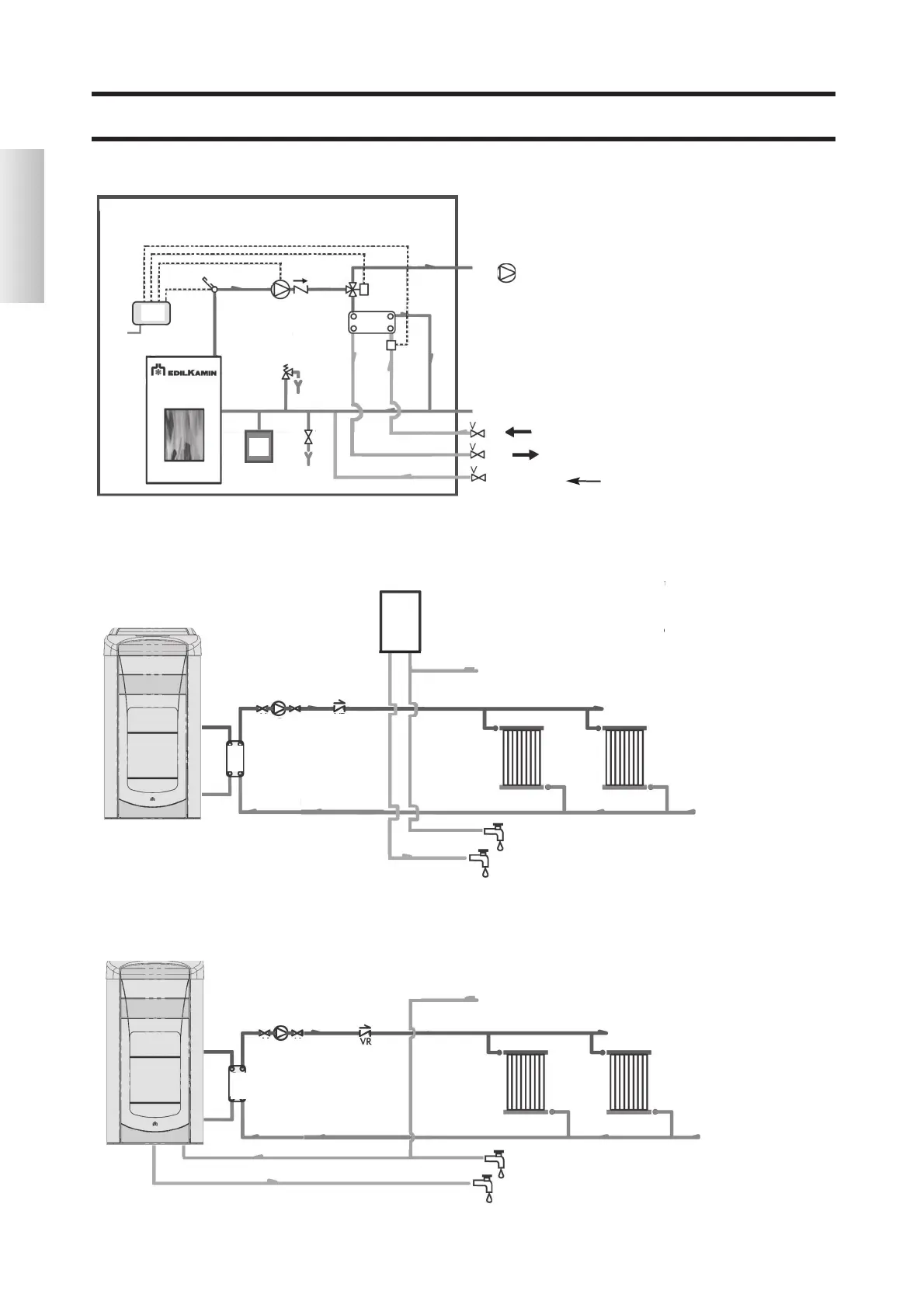
Heating system combined with boilers.
KEY
ACS: Domestic Hot Water
AF: Cold Water
MI: System delivery
P: pump (circulator)
Ra: Radiators
RI: System Return
Sc 30: 30 Plate Exchanger
V: Valve
VR: Non-return valve
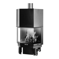
Heating system with single source of heat for the production of heat and domestic hot water
KEY
ACS: Domestic Hot Water
AF: Cold Water
MI: System delivery
EV: 3 way Solenoid valve
F: Flow meter
P: Pump (circulator)
Po: Pump OPTIONAL
RE: Electronic Regulator
RI: System Return
S: Drainage
Sc: Exchanger
ST: Temperature Probe
V: Valve
VE: Expansion tank
VR: Check Valve
VSP: Safety valve
VST: Thermal discharge valve
AF
MI
RI
VR
P
Sc
30
V
ACS
V
MI
RI
RA
RA
AF
F
AF
EV
MI
RI
VSP
ACS
VR
ST
P
Sc
RE
Power
V
S
VE
AF
ACS
AF
Refilling
heating system
KEY
ACS: Domestic Hot Water
AF: Cold Water
MI: System delivery
P: pump (circulator)
Ra: Radiators
RI: System Return
SB: boiler
Sc 30: 30 Plate Exchanger
V: Valve
VR: Non-return valve
AF
MI
RI
VR
SB
P
Sc
30
V
ACS
V
MI
RI
RA
RA
Po

 Loading...