- 27 -
ENGLISH
INSTALLATION
If combining with a pre-fabricated Edilkamin covering, to deŎ -
ne the exact positioning of the thermo Ŏ replace, it is important
to take the chosen covering model into consideration.
The positioning is implemented according to the model chosen
(refer to the installation instructions found inside the packaging
of each thermo Ŏ replace covering).
Always ensure the thermo Ŏ replace is level during the installa-
tion process.
- Drill a hole into the wall or the ŏ ooring for the external air
intake and connect the air adjustment mechanism to the hole as
described in the chapter called “external air inlet”.
- Use a stainless steel ŏ ue to connect the thermo Ŏ replace to the
chimney ŏ ue, adhering with the diameters indicated in the spe-
ciŎ cations table and the guidelines given in the chapter called
“chimney ŏ ues”.
- Verify that all moving parts function properly before setting
the thermo Ŏ replace covering in place.
- This system must be tested and ignited for the Ŏ rst time
before the covering is set in place.
INSTALLATION COVERING, FIREPLACE MAN-
TEL AND VENTILATION OUTLETS
The base of the thermo Ŏ replace covering must allow the
internal air to be recycled. Therefore, suitable slots or apertures
must be made for the air to pass through. Parts of the thermo
Ŏ replace covering that are made of marble, stone and bricks
must be mounted with a small gap between them and the Ŏ re-
place so as to prevent possible breakage due to expansion and
excessive overheating.
Wooden parts must be protected by Ŏ re resistant panels and
Practical advice
It is recommended to keep the radiators closed in the room
where the thermo Ŏ replace is installed; The heat emitted from
the outlet may be sufŎ cient to heat.
- An incomplete combustion process causes excessive fouling
on the heat exchanger pipe.
To prevent this you must:
- burn dry wood.
- ensure the hearth contains a bed of embers and burning car-
bon before adding more wood.
- place larger logs together with smaller ones.
- make sure the temperature of the return water is at least 50 °C
(use temperature control valve).
Igniting the Ŏ replace
- Ensure that at least one radiator is always open.
- Actuate the switches of the electronic regulator.
- Place a pile of medium-thin dry wood in the thermo Ŏ replace
and ignite the Ŏ re.
- Wait a few minutes until it reaches sufŎ cient combustion.
- Close the door
- Set the thermostat on the electronic regulator (*) at a tempera-
ture between 50 and 70° C.
NOTE: There may be a slight smell of paint the Ŏ rst few times
it is ignited, however, this will disappear quickly.
no part must touch the thermo Ŏ replace, on the contrary, there
must be an appropriate distance of at least 1 cm to allow the
air to ŏ ow, preventing heat accumulation. The Ŏ replace mantel
can be made of Ŏ reproof plasterboard panels or gypsum board
and, however, of completely Ŏ reproof material. Air should be
allowed to ŏ ow inside the Ŏ replace mantel (through the gap
between the door and the beam). Through convective motion,
the air will ŏ ow out from the grille installed at the top, resulting
in heat recovery and preventing excessive overheating.
The Ŏ replace mantel must have appropriate openings to carry
out maintenance on the Ŏ ttings.
In addition to that mentioned above, please consider the in-
dications stipulated in the UNI 10683 standard, paragraphs
4.4 and 4.7: “insulation, Ŏ nishing, Ŏ replace covering and
safety recommendations”.
Insulating mats must be applied when using an installation
KIT so as to protect it from the heat radiation emitted by
the thermo Ŏ replace.
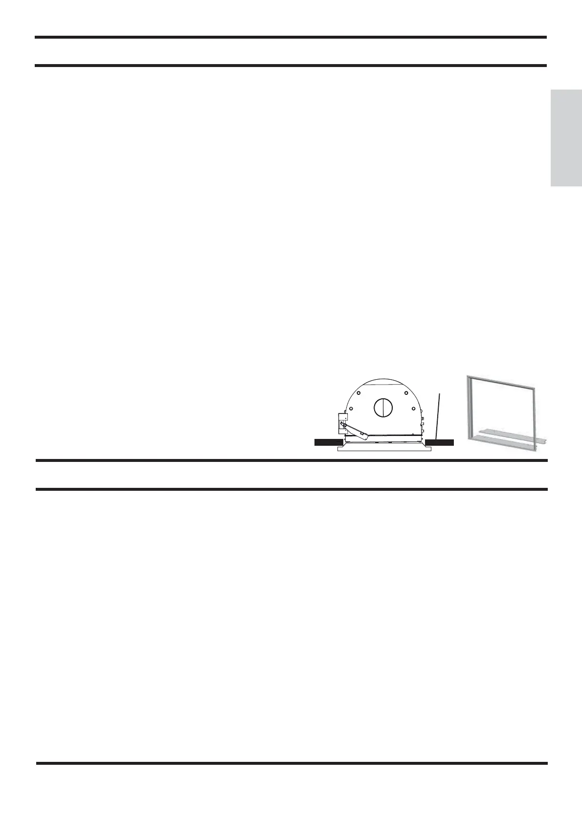
INLET FRAME (OPTIONAL)
To facilitate coupling with the covering’s components, the ther-
mo Ŏ replace can be Ŏ tted with a frame (A) to be applied on the
front of the inlet.
INSTRUCTIONS FOR USE
3-way valve
- During ignition the 3-way valve (*) diverts the ŏ ow of water,
forcing it to return directly to the thermo Ŏ replace;
when the set temperature is reached, the 3- way valve (*)
diverts the ŏ ow to the system (does not depend on the kit
installed).
By-pass damper
- When the door is closed, the by-pass damper automatically
diverts smoke, thus improving efŎ ciency.
- When the door is opened, the damper bypass opens automa-
tically, allowing the smoke to reach the smoke ŏ ue directly,
preventing it from coming out of the inlet.
Thermal Relief Valve
If the water temperature exceeds 90° C (e.g. because of too
much wood being placed in the hearth) the thermal relief valve
will be activated and the acoustic signal triggered.
In this case you must proceed as follows:
Do not load additional fuel and wait for the temperature to fall
below 80°C checking the warning lights on the electronic regu-
lator. The hot water tap can be opened to speed up the cooling
process if the thermo Ŏ replace is equipped with a hot sanitary
water production KIT.
A
(*) these components of the system are to be provided by the installer.
Plasterboard
A
 Loading...