This document is a detailed instruction manual for an Eduard 1/32 scale photo-etched detail set designed for the Tamiya F-4J Phantom II model kit. It provides comprehensive visual guidance and textual cues for enhancing the model with intricate photo-etched parts.
Function Description:
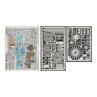
The primary function of this detail set is to significantly enhance the realism and detail of a 1/32 scale Tamiya F-4J Phantom II model. It achieves this by replacing or augmenting existing plastic parts with finely crafted photo-etched metal components, which offer a level of thinness and intricate detail not achievable with injection-molded plastic. The set covers various areas of the aircraft, including the cockpit, landing gear bays, exterior surfaces, and other structural elements, providing a more accurate and visually appealing representation of the real aircraft.
Usage Features:
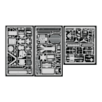
The manual is structured to guide the modeler through the assembly process step-by-step, using a combination of exploded diagrams and numbered parts. Each step clearly indicates which original kit parts are to be modified or removed, and which photo-etched parts are to be added.
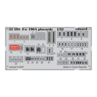
- Part Identification: Parts are clearly labeled with numbers, and different types of parts are distinguished by color: blue for photo-etched parts, black for original kit parts, and green for parts to be removed. This color-coding system helps modelers quickly identify the components needed for each step.
- Symbolic Instructions: A set of universal symbols is used to convey specific actions:
- APPLY EXPRESS MASK AND PAINT BEFORE GLUING: Indicates that a part should be masked and painted before being attached.
- SYMETRICAL ASSEMBLY: Denotes that a part or assembly needs to be mirrored for the opposite side of the model.
- REMOVE: Instructs the modeler to cut away or eliminate a specific section of an original kit part.
- GRIND: Advises the modeler to sand down or smooth a part.
- DRILL HOLE: Indicates where a hole needs to be drilled, often accompanied by diameter and depth specifications for plastic parts (e.g., Ø - 0,5mm, l - 1mm plastic).
- PARTS TO BE REMOVED: Highlights specific sections of plastic parts that need to be cut off.
- BEND: Shows where a photo-etched part needs to be folded or shaped.
- OPTION: Suggests alternative parts or assembly methods, allowing for variations in the model's appearance.
- REPLACE: Indicates that an original kit part should be substituted with a photo-etched part.
- FILL: Instructs the modeler to use putty or filler to smooth gaps or unwanted details.
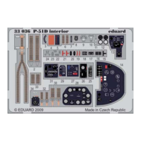
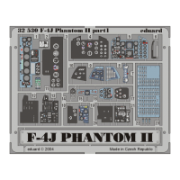
- Cockpit Detailing: The manual provides extensive instructions for detailing the cockpit, including instrument panels (H16, H19, H23), side consoles, and ejection seat components. This involves carefully bending and layering photo-etched parts to create multi-dimensional instrument faces and controls. Film parts (e.g., film B, film F, film A, film C, film D, film E) are used in conjunction with photo-etched bezels to represent instrument glass, adding depth and realism.
- Landing Gear Bays: Detailed steps are provided for enhancing the nose landing gear bay (J13) and main landing gear bays. This includes adding structural elements, wiring, and hydraulic lines using photo-etched parts and specified plastic rod diameters (e.g., Ø - 0,5mm, l - 10mm plastic).
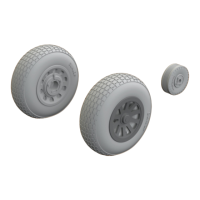
- Exterior Enhancements: Various exterior details are addressed, such as wing fences (24, 25), fuselage vents (38, 37), and exhaust nozzle details (J34, 72, 77, 92). The manual also covers details for the landing gear struts (B25+B54+, B1+B30, B2+B31), including brake lines and other small components.
- Fuselage and Wing Structure: Instructions for adding internal fuselage structure (e.g., 26, 27, 88, 89) and wing details (e.g., 56, J20+J21+J37+J38) are included, often requiring the removal of existing plastic details before the photo-etched parts are applied.
- Small Parts Assembly: Many steps involve the assembly of very small photo-etched parts, requiring precision and careful handling. For example, the ejection seat components (53, 54) and various levers and switches in the cockpit.
- Material Specifications: For parts that need to be scratch-built or modified, the manual provides specific material dimensions, such as plastic rod diameters and lengths (e.g., Ø - 0,5mm, l - 1mm plastic; Ø - 1mm, l - 2mm plastic; Ø - 0,5mm, l - 7mm plastic; Ø - 1mm, l - 3mm plastic).
- References: The manual includes a list of reference materials used in the design of the detail set, such as "Famous Airplanes Of The World # 114 (10/1979) - F-4J/K Phantom II," "Detail & Scale #12 - F-4 Phantom II," and "Verlinden Publ. - LOCK ON #8 - F-4E PHANTOM II." These references can be valuable for modelers seeking additional information or visual guides for super-detailing their model.
Maintenance Features:
As this is a detail set for a plastic model, "maintenance" primarily refers to the care and handling of the photo-etched parts and the finished model.
- Handling Photo-Etched Parts: Photo-etched parts are delicate and can be easily bent or damaged if not handled carefully. Modelers should use fine-tipped tweezers and a sharp hobby knife or specialized photo-etch shears to remove parts from the fret.
- Adhesive Application: The manual implicitly requires the use of appropriate adhesives, such as super glue (cyanoacrylate) for attaching photo-etched parts, and plastic cement for original kit parts. Care must be taken to apply glue sparingly to avoid obscuring fine details.
- Painting: The instruction to "APPLY EXPRESS MASK AND PAINT BEFORE GLUING" highlights the importance of pre-painting certain components, especially those with intricate details or multiple layers, to achieve a clean finish.
- Storage: Unused photo-etched parts should be stored safely in their original packaging or a similar protective container to prevent loss or damage.
- Finished Model Care: Once assembled, the detailed model should be handled with care to avoid breaking off delicate photo-etched parts. Regular dusting with a soft brush or air blower can help maintain its appearance.
In summary, this Eduard detail set manual provides a comprehensive guide for transforming a standard Tamiya F-4J Phantom II model into a highly detailed and accurate replica, emphasizing precision assembly and careful handling of delicate components.