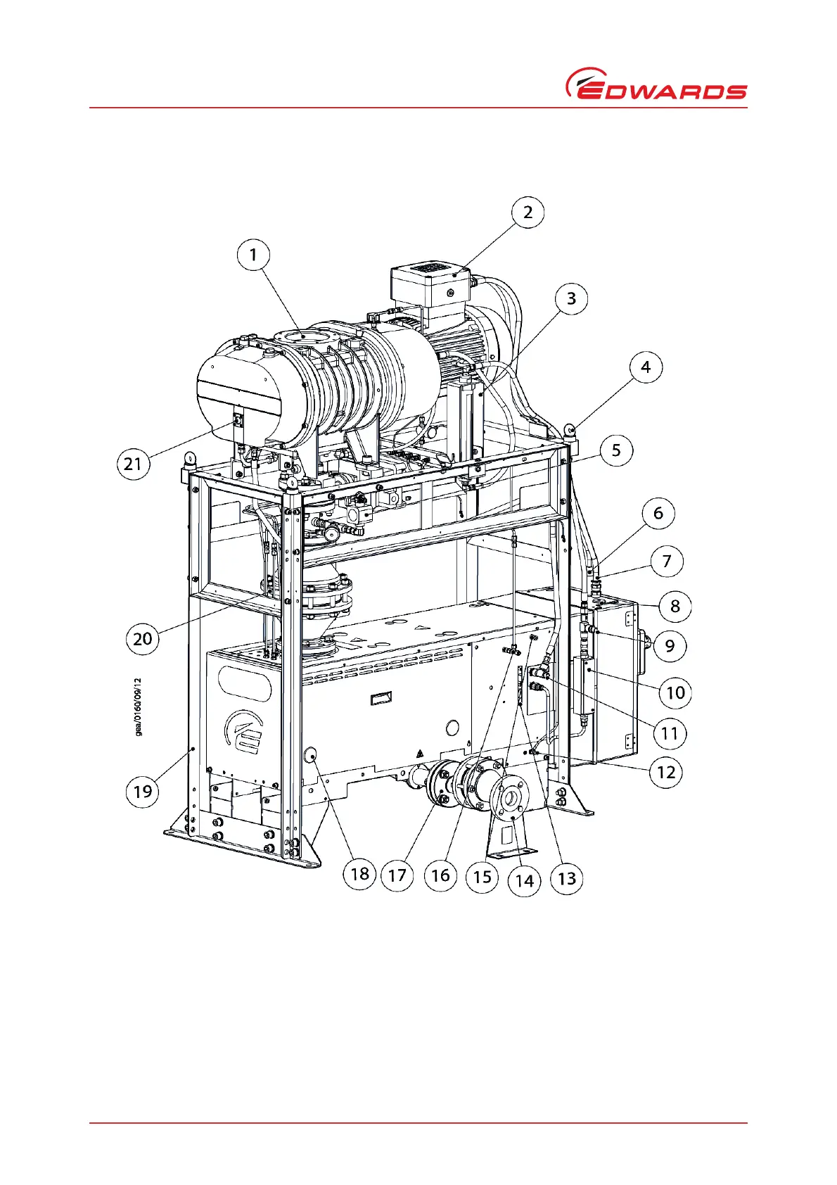
1. System inlet flange (ISO 160)
2. Booster motor terminal box
3. Water flow switch
4. System lifting eyebolts (4 off)
5. CXS inlet isolation valve
6. Booster motor thermistor cable
7. Booster motor power cable
8. Mains power connection
9. System cooling water outlet (3/8 inch BSPT male)
10.CXS pump cooling water flow meter
11.System cooling water inlet (3/8 inch BSPT male)
12.Customer Protective Earth connection (M8)
13.CXS Shaft seal purge flowmeter
14.Exhaust flange (DN50 / 2” ANSI)
15.Air supply connection (1/4 inch tube fitting)
16.Nitrogen purge connection (1/4 inch tube fitting)
17.CXS exhaust flame arrester (dependent on variant)
18.Grommets for CXS sight glass access (2 off)
19.Booster support frame
20.CXS inlet flame arrester (dependent on variant)
21.Booster oil level sight glass (gear cover)