11
EGS Series Quick Start User Manual
Version 01 - 2020
24V
COM
0V
13
D1
14
D2
22
21
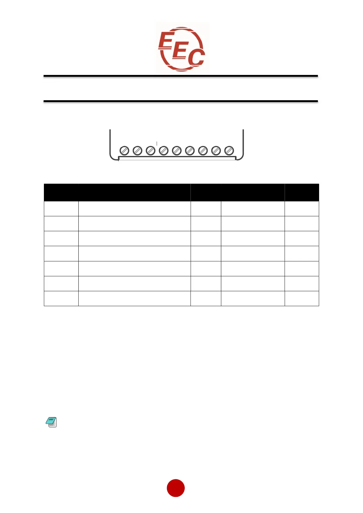
Control Terminal Connections
Control Terminal Functions
#1 24Vdc Specification: See General Specification (page 19) for VA rating, residual ripple < 100mV,
spikes/switching peaks < 240mV, Turn On/Off response no overshoot of Vout, Overvoltage voltage protection
output voltage must be clamped <30Vdc
#2 The voltage applied to the digital inputs D1 and D2 must not exceed 24Vdc
#3 250Vac, 2A, Cosø =0.5
Digital Input 2 (D2) Selectable Functions
Different functions may be assigned to Digital Input 2 in the I/O menu. Available assignments are:
Reset
Hold Start Ramp
Enable
Fire Mode
In Fire Mode all trips are disabled.
Digital Outputs13,14, 21,22 Selectable Functions
The outputs may be mapped to Fault or Top-of-Ramp, Auto Reset Pending or Exceeded.
Terminal Description Default Function Selectable Note
24Vdc Control Supply +Us - No #1
0V Control Supply -Us - No
COM Digital Inputs Common - No
D1 Digital Input 1 - No #2
D2 Digital Input 2 - Yes #2
13/14 Main Contactor Control (Run Relay) - Yes #3
21/22 Fault Relay - Yes #3
Electrical Installation (continued)


 To Next Page