Do you have a question about the EEC SE Series and is the answer not in the manual?
Explains product marking and cautionary symbols for safety.
Defines key technical terms used in electrical safety testing.
Covers safety precautions, service, maintenance, test station, and operator requirements.
Details various safety tests like Dielectric Withstand, Insulation Resistance, and Ground Bond.
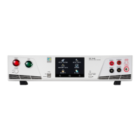
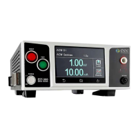
Highlights the main features and benefits of the SE Series electrical safety analyzers.
Guides on unpacking, inspecting the instrument, and retaining packaging materials.
Covers instrument installation, including work area requirements and power connections.
Provides detailed technical specifications for different SE Series models.
Introduces the instrument's controls, covering front and rear panel elements.
Describes the function of the instrument's main power switch for turning it on or off.
Explains the touch screen's role in displaying information and controlling the instrument.
Guides on navigating and operating the instrument via its touch screen interface.
Describes the instrument's main menu screen and its available options upon power-up.
Details how to configure system parameters like time, date, calibration, and hardware.
Covers hardware-related system settings including Smart GFI, PLC Remote, and Screensaver.
Details the barcode function for inputting product and serial number information for testing.
Outlines security features, including user access levels and password protection.
Guides on importing and exporting system settings and test file data via USB.
Covers user interface settings like results display, touch sound, alarm volume, and language.
Explains how to configure the display of test results (ALL, LAST, or Pass/Fail).
Details the FAILCHEK process for verifying the instrument's failure detection circuitry.
Outlines the procedure for performing Continuity FAILCHEK to verify continuity detection.
Details the procedure for performing Ground Bond FAILCHEK to verify ground bond detection.
Explains the procedure for performing AC Hipot FAILCHEK to verify AC Hipot detection.
Details the procedure for performing DC Hipot FAILCHEK to verify DC Hipot detection.
Outlines the procedure for performing IR FAILCHEK to verify Insulation Resistance detection.
Describes various test parameters available for configuring tests.
Explains each test parameter, including Test Type, Voltage, and limits.
Explains the Offset function used to compensate for test lead and fixture resistance in continuity tests.
Guides on creating and configuring new test files and steps.
Details the specific parameters and settings for performing an ACW test.
Details the specific parameters and settings for performing a DCW test.
Details the specific parameters and settings for performing an IR test.
Details the specific parameters and settings for performing a GND test.
Details the specific parameters and settings for performing a Continuity test.
Explains how to navigate and display previously created test files.
Provides instructions on how to select and execute test files and steps.
Explains the correct procedure for connecting test leads to the instrument's receptacles.
Describes the Remote Interlock feature and its function for safety lockout.
Lists and explains various error and fail messages displayed by the instrument during testing.
Explains fatal error messages and the need to contact customer support for assistance.
Describes the remote signal outputs (PASS, FAIL, PROCESSING) for external monitoring.
Explains remote signal inputs for test control and selecting pre-programmed test files.
Details the RS-232 interface, including its commands and capabilities.
Specifies the required COM port settings for RS-232 communication.
Describes the optional GPIB interface and its connectivity.
Explains how to set the unique address for GPIB devices.
Lists the various interface functions supported by the instrument.
Provides a comprehensive list of commands for controlling the instrument via USB, RS-232, and GPIB.
Details commands for editing individual test parameters and their syntax.
Details commands for editing system parameters and their syntax.
Lists query commands used to retrieve instrument data, results, and status information.
Lists standard IEEE 488.2 common commands required for instrument control and status reporting.
Outlines the standard one-year warranty and options for extended coverage.
Explains the procedure for entering the instrument into calibration mode.
Guides on selecting and calibrating specific parameters using test equipment.
| Brand | EEC |
|---|---|
| Model | SE Series |
| Category | Measuring Instruments |
| Language | English |