EasyManua.ls Logo

EEC SE 7440 User Manual

Default Icon
106 pages
To Next Page IconTo Next Page
Page #1 background imageLoading...
Page #1 background image
SE Series
SE 7430/SE 7440/SE 7441/SE 7451/SE 7452
Electrical Safety Analyzer
User Manual
E2.00

Table of Contents

Question and Answer IconNeed help?

Do you have a question about the EEC SE 7440 and is the answer not in the manual?

EEC SE 7440 Specifications

General IconGeneral
Display Type3 1/2 digit LCD
Power Supply9V battery
Operating Temperature0 to 50°C
Dimensions135 x 70 x 35 mm
Weight200g

Summary

Specifications and Controls

3.1 Specifications

Detailed technical data and performance characteristics of the instrument.

3.2 Instrument Controls

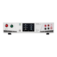
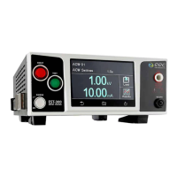
Identification and function of front and rear panel controls.

Programming Instructions

4.8 PERFORM TESTS

Steps and guidance for executing programmed tests on the DUT.

CALIBRATION

9.3 Calibration of Parameters

Steps for calibrating specific instrument parameters.

9.2 Calibration Initialization

Procedure for entering the instrument's calibration mode.

Introduction

1.1 Safety Symbols

Symbols indicating safety precautions and potential hazards.

Safety

Safety

1.3.3 Test Operator

Qualifications and responsibilities of personnel operating the instrument.

Safety

1.3.4 Instrument Connections

Instructions for safely connecting test leads and the instrument.

1.3.5 Device Under Test

Safety precautions when interacting with the device being tested.

Safety

1.3.6 Key Safety Points to Remember

A concise list of critical safety instructions for operation.

Introduction to Product Safety Testing

The Different Types of Safety Tests

1.5.1 Dielectric Withstand Test

Principle and applications of dielectric voltage-withstand testing.

1.5.5 Touch Current Test

Measuring leakage current to ensure user safety.

Key Features and Benefits: SE Series

Instrument Controls

3.2.1 Front Panel Controls

Identification and function of the instrument's front panel buttons and displays.

3.2.2 Rear Panel Controls

Identification and function of the instrument's rear panel connectors and ports.

Programming Instructions

Programming Instructions

Setup System

FAILCHEK

Test Parameters

PERFORM TESTS

Bus Remote Interface GPIB / USB / RS-232

USB/RS-232 / GPIB Interface Command List

USB/RS-232 / GPIB Interface Command List

Related product manuals