16
Italiano FrançaisEnglish
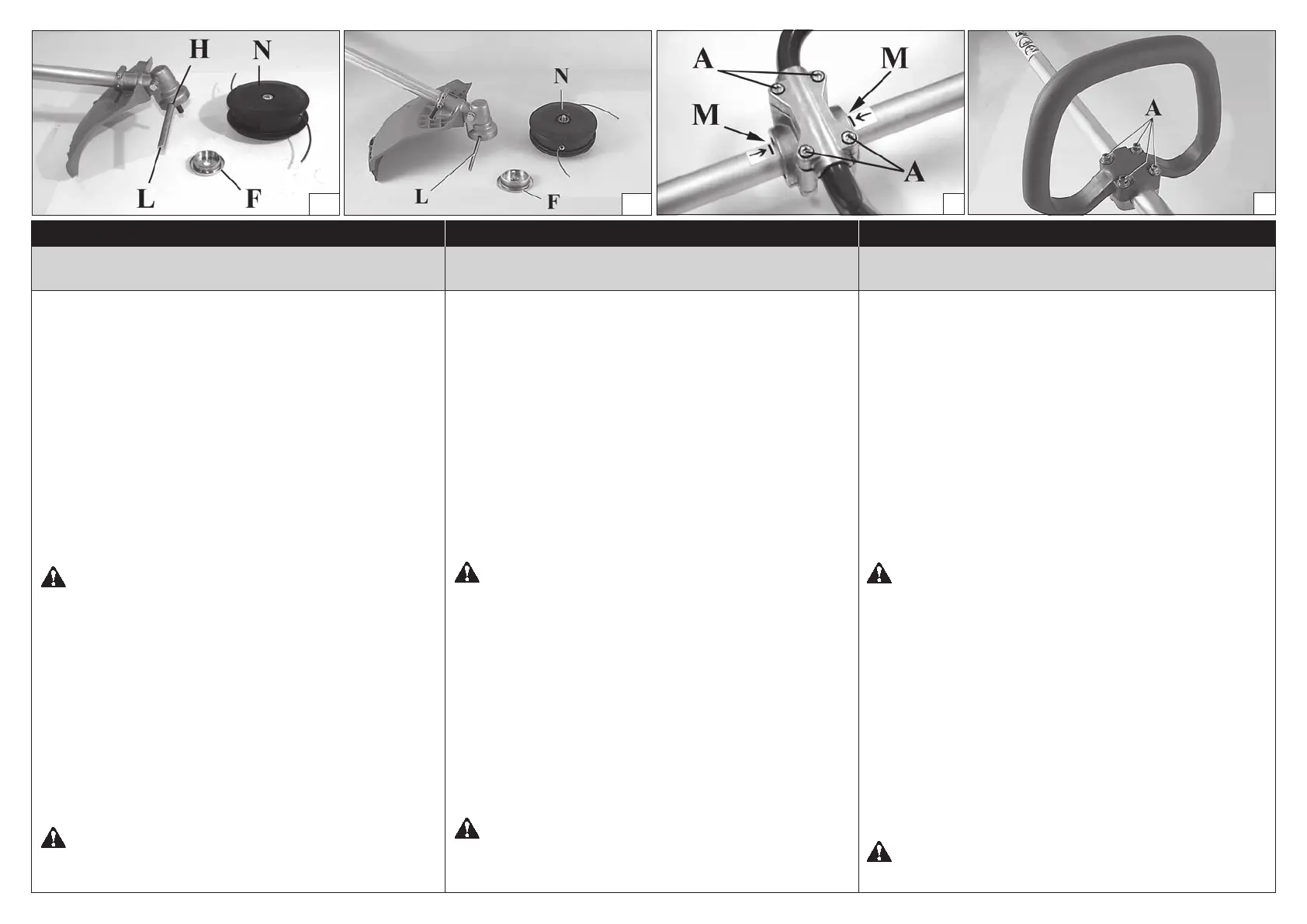
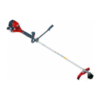
FITTING THE NYLON LINE HEAD (Fig. 9 A-B)
Put the upper (F) ange in place. Put the head xing
pin (L) in the appropriate hole (H) and tighten the head
(N) anti-clockwise by hand.
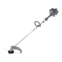
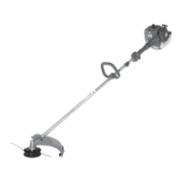
FITTING THE HANDLE (Figs. 10-11)
Fit the handle onto the sha arm and secure it using
screws (A), washers, and nuts. e handle position
is calculated depending on the requirements of the
operator.
WARNING!: e handle must be xed between
the two notches (M, Fig.10) indicated on the drive sha
tube.
ASSEMBLING THE SAFETY BOOM (Fig. 12)
When using the disc instead of nylon line head, it is
necessary to set up the “safety boom”. Fix the boom
(A) under the attachment of handle (C) by means of
the screws (B). Taking care to verify the “safety boom”
being on the le side of the brushcutter.
WARNING: Make sure that all components are
connected properly and all screws tightened.
ASSEMBLAGGIO ASSEMBLAGEASSEMBLY
MONTAGGIO TESTINA A FILI DI NYLON
(Fig. 9 A-B)
Inserire la angia superiore (F). Inserire il perno fermo
testina (L) nell’apposito foro (H) ed avvitare in senso
antiorario la testina (N) con la sola forza delle mani.
MONTAGGIO IMPUGNATURA (Fig. 10-11)
Montare l'impugnatura sul tubo di trasmissione e
ssarla tramite viti (A), rondelle e dadi. La posizione
dell'impugnatura è registrabile in funzione all'esigenza
dell'operatore.
ATTENZIONE!: L’impugnatura deve essere ssata
all’interno delle due tacche (M, Fig.10) indicate sul tubo
di trasmissione.
MONTAGGIO BARRIERA DI SICUREZZA (Fig. 12)
Quando si utilizza il disco anziché la testina a li di
nylon è necessario montare la “barriera di sicurezza”.
Fissare la barriera (A) sotto l’attacco impugnatura (C)
tramite le viti (B), avendo l’accortezza di veri care che
la “barriera di sicurezza” stessa risulti sul lato sinistro
del decespugliatore.
AT TENZIONE: Assicurarsi che tutti i componenti
del decespugliatore siano ben collegati e le viti serrate.
MONTAGE DE LA TETE AUX FILS DE NYLON
(Fig. 9 A-B)
En lez la bride supérieure (F). En lez le goujon qui
va bloquer la tête (L) dans son ori ce (H) et vissez à la
main, dans le sens contraire des aiguilles d'une montre,
la tête (N).
MONTAGE DE LA POIGNEE (Fig. 10-11)
Montez la poignée sur le tuyau de transmission et xez-la
avec les vis (A), les rondelles et les écrous. La position
de la poignée se règle selon les exigences de l'opérateur.
ATTENTION!: Fixer la poignée à l’intérieur des
deux crans (M, Fig. 10) indiqués sur le tuyau de
transmission.
MONTAGE DE LA BARRIÈRE DE SÉCURITÉ
(Fig. 12)
En utilisant le disc à la place de la tête nylon, il est
nécessaire de monter la “barrière de sécurité”. Fixer
la barrière (A) sous le support de la poignée (C) au
moyen des vis (B), en prendant bien soin de véri er
pue la “barrière de sécurité” même sait du côte gauche
de la débroussailleuse.
ATTENTION: Veillez à ce que tous les
composants soient bien relié et les vis serrées.
9A 9B
10
11