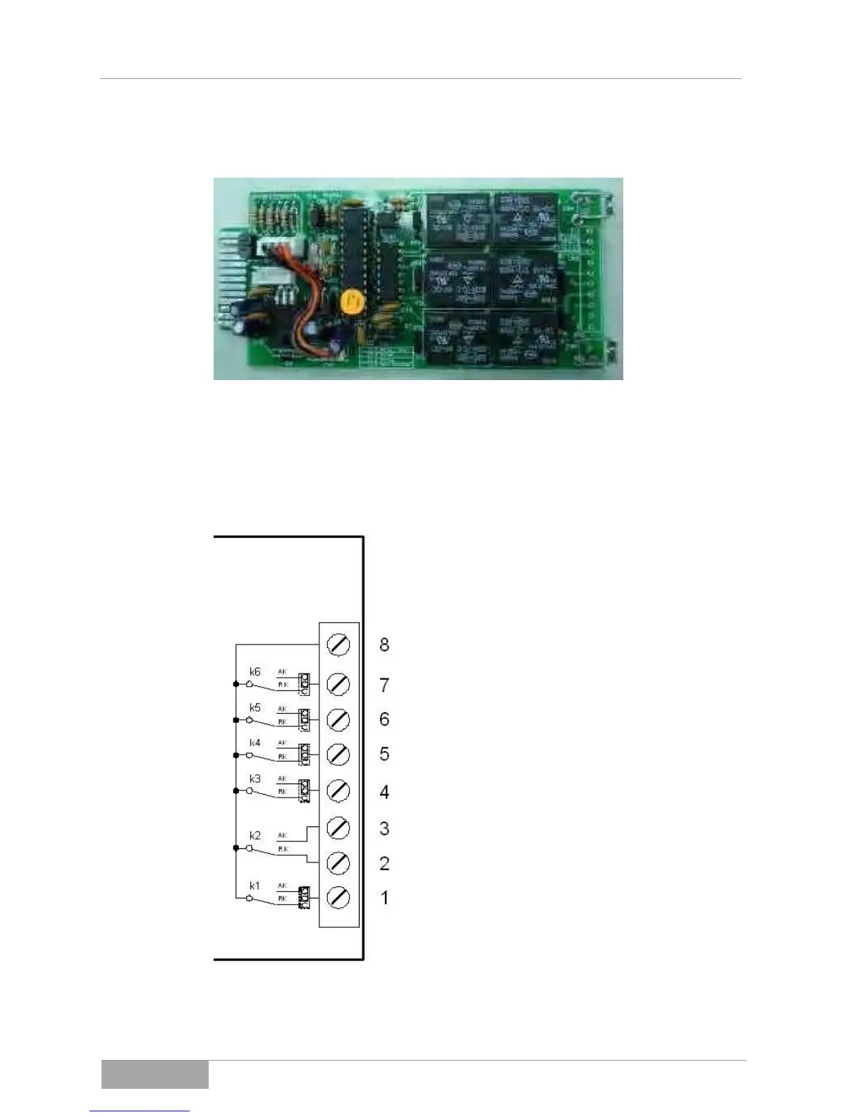
8.3.5 Relay contact card (DCE-B card)
Fig. 8-3-5 - 1 Relay contact card (DCE-B card)
The pin assignment of the 10 pin terminal
1 Pin 1:
One DC input voltage within and one DC
input voltage below the range
2 Pin 2:
At least one DC input above the minimum
limit
3 Pin 3:
All DV input voltage below the minimum
limit
4 Pin 4:
Frequency of the AC output (mains)
outside the tolerance
5 Pin 5:
Isolated operation switched off
6 Pin 6:
Output current of the photovoltaic solar
inverter above the tolerance
7 Pin 7:
The cooling element temperature of the
photovoltaic solar inverter is too high
8 Pin 8:
Common
Fig. 8-3-5 - 2 The pin assignment of the 10 pin terminal