Do you have a question about the Effekta ES4200 and is the answer not in the manual?
Introduction to the operating manual and its purpose for the user.
Defines manual scope and provides storage instructions for the operating manual.
Explains abbreviations, general symbols, and danger warning levels used in the manual.
Details DANGER!, WARNING!, and CAUTION! hazard levels and their implications.
Explains specific warning symbols and symbols for instructions like 'Take note'.
Explains symbols for tasks, cross-references, figure positions, recycling, and disposal.
Mandates understanding manual points and details warranty terms and conditions.
Excludes liability for damage and provides guidelines for transporting/storing the inverter.
Specifies safe installation locations and environmental conditions for the inverter.
States inverter safety and defines intended use vs. improper uses causing harm.
Emphasizes preventing injury/damage and returning product for environmentally friendly disposal.
Details safety requirements for connecting the inverter, including voltage matching and grounding.
Provides safety advice regarding electrical dangers and handling live components.
States inverter readiness and details safety for connecting PV modules.
Warns of shock risks during maintenance and requires licensed mains connection.
Provides physical dimensions (Height, Width, Depth) for ES2200/ES3300 and ES4200/ES5000 models.
Details the front panel display, LED indicators, and connection interfaces for ES2200/ES3300.
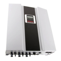
Details the front panel display, LED indicators, and connection interfaces for ES4200/ES5000.
Provides instructions and dimensions for mounting the inverter's wall bracket securely.
Specifies optimal temperature, humidity, and ventilation requirements for inverter installation.
Details vertical assembly, heat dissipation, and minimum spacing requirements around the inverter.
Provides safety precautions and steps for physically mounting the inverter using the wall mount.
Details safety precautions and steps for connecting the AC power cable to the inverter.
Details module requirements and connectors for inverter compatibility.
Explains connecting PV strings using MC4 connectors and DC circuit breaker safety.
Guides on determining PV string panels, voltage limits, and module compatibility.
Illustrates cabling for ES4200/ES5000 models using DC disconnectors.
Details the LCD display, LED indicators, and operating keys on the inverter's control panel.
Lists checks for housing, DC cables, AC cable, and AC switch before starting the inverter.
Guides on initial startup, including turning on DC breaker and observing LCD displays.
Explains how to set country, operating mode, and assign unique ID numbers to the inverter.
Steps for final commissioning, including checking breakers and observing status displays.
How to check various readings like feed power, temperatures, voltages, and currents on the LCD.
Describes normal, standby, error, EPO, and shutdown states with LCD and LED indicators.
Details the standard RS232 serial interface, its settings, and pin assignment.
Information on compatibility and support for Solar-Log™ monitoring systems.
Explains how to install optional communication cards like RS485, USB, SNMP.
Details the RS485 card, its definition, and connection pin assignments.
Shows wiring diagrams for connecting multiple inverters to Solar-Log or a PC via RS485.
Details the USB card, its definition, and pin assignment for connectivity.
Explains the relay contact card and the pin assignment for various functions.
Information on the SNMP card and where to find installation advice.
Lists and explains error codes (Er00-Er08) and provides troubleshooting steps.
Lists and explains mains error codes (AL00-AL14) and provides troubleshooting steps.
Provides contact information for service, including phone, fax, and email addresses.
Details technical specifications like technology, input/output data, and AC voltage range.
Schematic diagram illustrating the internal components and connections of ES2200/ES3300 models.
Schematic diagram illustrating the internal components and connections of ES4200/ES5000 models.
Lists included items and optional accessories with article numbers and descriptions.
| Output Waveform | Pure sine wave |
|---|---|
| Maximum PV Array Power | 5000W |
| Max. Charging Current | 80A |
| Model | ES4200 |
| Output Voltage | 230V AC |
| Output Frequency | 50Hz/60Hz |
| Protection | Overload, Overheating, Short Circuit |
| Cooling | Fan |