EasyManua.ls Logo

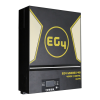
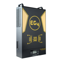
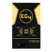
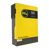
EG4 6500 EX-48 User Manual

EG4 6500 EX-48
80 pages
To Next Page IconTo Next Page
Page #1 background imageLoading...
Page #1 background image
May 2022 | Rev A | Information subject to change without notice.
6.5KVA 120Vac
6500 EX-48
EG4 Electronics
www.eg4electronics.com

Questions and Answers:

EG4 6500 EX-48 Specifications

General IconGeneral
ModelEG4 6500 EX-48
Rated Power6500W
Input Voltage48VDC
Output WaveformPure Sine Wave
Efficiency93%
Max PV Array Power8000W
Max DC Voltage500V
MPPT Voltage Range120 - 450V
Battery Voltage48V
Max Charging Current120A
AC Output Voltage120V/240V
Max Output Current27A

Summary

About This Manual

Purpose

Describes the assembly, installation, operation, and troubleshooting of the unit.

Scope

Provides safety and installation guidelines, as well as information on tools and wiring.

Safety Instructions

SAFETY INSTRUCTIONS

Contains important safety and operating instructions for the unit.

Introduction

Features

Lists key features of the residential self-consumption multi-function inverter.

Basic System Architecture

Illustrates the basic application and required devices for a running system.

Product Overview

Product Overview

Details the components and ports of the EG4 6500EX-48 inverter.

Installation

Unpacking and Inspection

Instructions for inspecting the unit and its package contents after delivery.

Installation of Battery Wiring Extension Box, Cable Glands, and Conduit Fittings 1/2" or 3/4"

Guidance on installing the battery wiring extension box and associated fittings.

Installation

Preparation

Steps before connecting wirings, including removing the bottom cover.

Mounting the Unit

Guidelines for selecting the optimal installation location and ensuring proper clearance.

Battery Connection

Battery Connection

Detailed instructions for connecting the battery, including cable size and torque values.

AC Input/Output Connection

AC Input/Output Connection

Procedures for connecting AC input and output, including cable requirements and polarities.

PV Connection

PV Connection

Guidelines for connecting PV modules, including breaker requirements and module types.

PV Connection

Recommended Panel Configuration

Recommendations for PV module configuration based on voltage and power parameters.

Final Assembly

Final Assembly

Steps for completing the assembly after wiring, including re-connecting cables and the bottom cover.

Remote Display Panel Installation

Instructions for detaching and installing the LCD module in a remote location.

Remote Display Panel Installation

Remote Display Panel Installation (continued)

Steps for mounting the LCD module and connecting it to the inverter via a communication cable.

Communication Connection

Serial Connection

Instructions for connecting the inverter to a PC using a serial cable.

Wi-Fi Connection

Details on enabling wireless communication using the Wi-Fi transmitter and the WatchPower app.

Dry Contact Signal

Information on the dry contact signal for external device notification.

BMS Communication

Requirement for a special communication cable for Lithium-Ion battery banks.

OPERATION

Power ON/OFF

How to turn the unit on and off using the display panel switch.

Inverter Start-Up

Describes the initialization sequence and RGB LED bar behavior during startup.

Operation and Display Panel

Overview of the operation panel, including indicators, function keys, and LCD display.

Operation and Display Panel

Function Keys

Details the function keys and their descriptions for operating the inverter.

LCD Display Icons

Explains the icons used on the LCD display for various information categories.

LCD Display Icons

LCD Display Icons (continued)

Further explanation of LCD display icons for battery status, load, and operation modes.

LCD Setting

General Setting

How to enter the Settings Menu and navigate through program settings.

Program 00: Exit setting mode

Option to exit the current setting mode or program.

Program 01: Output source priority

Configures load power source priority (Utility, USB, SBU).

LCD Setting

Program 02: Maximum charging current

Sets the total charging current for solar and utility chargers.

Program 03: AC input voltage range

Defines acceptable AC input voltage ranges (Appliances, UPS).

Program 05: Battery type

Selects the battery chemistry (EG4, Flooded, AGM, User-Defined, etc.).

LCD Setting

Program 06: Auto restart when overload occurs

Configures the unit's behavior upon overload detection (restart or disable).

Program 07: Auto restart when over temperature occurs

Configures the unit's behavior upon over-temperature detection (restart or disable).

Program 09: Output frequency

Sets the output frequency (50Hz or 60Hz).

Program 10: Output voltage

Sets the output voltage (110V or 120V).

LCD Setting

Program 11: Maximum utility charging current

Sets the maximum charging current from the utility input.

Program 12: Setting voltage point back to utility source

Sets voltage point for switching back to utility source in SBU mode.

Program 13: Setting voltage point back to battery mode

Sets voltage point for switching back to battery mode in SBU mode.

Program 16: Charger source priority

Configures charger source priority (Solar, Utility, or both).

LCD Setting

Program 16: Charger source priority (cont.)

Configures charger source priority (Solar and Utility, Only Solar).

Program 18: Alarm control

Controls alarm and buzzer settings.

Program 19: Auto return to default display screen

Sets whether the screen returns to default after inactivity.

Program 20: Backlight control

Controls the LCD screen backlight function.

LCD Setting

Program 22: Beeps while primary source is interrupted

Configures audible alerts for primary source interruptions.

Program 23: Overload bypass

Enables/disables bypass mode during overload in battery mode.

Program 25: Record Fault code

Enables or disables recording of fault codes.

Program 26: Bulk charging voltage

Sets the bulk charging voltage based on battery type.

Program 27: Floating charging voltage

Sets the floating charging voltage based on battery type.

Program 28: AC output mode

Configures AC output mode for single, parallel, or 3-phase applications.

LCD Setting

Program 28: AC output mode (cont.)

Configures AC output mode for split-phase applications (120°/180° difference).

Program 29: Low DC cut-off voltage

Sets the voltage point for low DC cut-off.

Program 30: Battery equalization

Enables or disables battery equalization function.

LCD Setting

Program 31: Battery equalization voltage

Sets the voltage for battery equalization.

Program 33: Battery equalized time

Sets the duration for battery equalization.

Program 34: Battery equalized timeout

Sets the timeout for battery equalization.

Program 35: Equalization interval

Sets the frequency or interval for battery equalization.

Program 36: Equalization activated immediately

Activates battery equalization immediately.

Program 37: Reset all stored data for PV generated power and output load energy

Resets stored data related to PV generation and load energy.

LCD Setting

Program 41: Maximum discharging current

Sets the maximum battery discharging current.

Program 51: On/Off control for RGB LED

Controls the RGB LED lighting function on/off.

Program 52: Brightness of RGB LED

Adjusts the brightness of the RGB LED.

Program 53: Lighting speed of RGB LED

Adjusts the speed of the RGB LED lighting.

LCD Setting

Program 54: RGB LED effects

Selects different effects for the RGB LED lighting.

Program 55: Color combination of RGB LED

Sets color combinations for RGB LED to show energy status.

Program 93: Erase all data log

Erases all logged data.

Program 94: Data log recorded interval

Sets the interval for recording data logs.

LCD Setting

Program 94: Data log recorded interval (cont.)

Sets the interval for recording data logs (30, 60 minutes).

Program 95: Time setting – Minute

Sets the minute value for the system time.

Program 96: Time setting - Hour

Sets the hour value for the system time.

Program 97: Time setting- Day

Sets the day value for the system time.

Program 98: Time setting- Month

Sets the month value for the system time.

Program 99: Time setting - Year

Sets the year value for the system time.

Function Setting

USB Function Setting

Instructions for using the USB port for firmware upgrade, data log export, etc.

Function Setting

Timer Setting for Output Source Priority

Sets daily timers for output source priority (Utility, Solar, SBU).

Function Setting

Timer Setting for the Charger Source Priority

Sets daily timers for charger source priority (Solar, Solar & Utility, Solar Only).

LCD Display

LCD Display

Explains how to switch information on the LCD display using UP/DOWN buttons.

Input voltage/Output voltage

Displays input and output voltage information.

Input frequency

Displays input frequency information.

LCD Display

PV voltage

Displays PV voltage for PV1 and PV2 inputs.

PV current

Displays PV current for PV1 and PV2 inputs.

LCD Display

PV power

Displays PV power for PV1 and PV2.

Charging current

Displays AC, PV, and combined charging currents.

Charging power

Displays AC, PV, and combined charging power.

Battery voltage and output voltage

Displays battery voltage and output voltage.

Output frequency

Displays output frequency.

Load percentage

Displays the current load percentage.

LCD Display

Load in VA

Displays load in Volt-Amperes.

Load in Watt

Displays load in Watts.

Battery voltage/DC discharging current

Displays battery voltage and DC discharging current.

PV energy generated today and Load output energy today

Shows daily PV energy generation and load output energy.

LCD Display

PV energy generated this month and Load output energy this month.

Shows monthly PV energy generation and load output energy.

PV energy generated this year and Load output energy this year.

Shows yearly PV energy generation and load output energy.

PV energy generated totally and Load output total energy.

Shows total PV energy generation and load output energy.

Real date.

Displays the current real date.

Real time.

Displays the current real time.

Main CPU version checking.

Displays the main CPU version.

Operating Mode Description

Operating Mode Description

Describes different operating modes: Standby, Line, Battery.

Operating Mode Description

Line Mode

Details operation in Line Mode with different source priorities and charging.

Operating Mode Description

Battery Mode

Details operation in Battery Mode, powering from battery and/or PV.

Faults Reference Code

Faults Reference Code

Lists fault codes, their events, and corresponding icons.

Warning Indicator

Warning Indicator

Lists warning codes, events, audible alarms, and icon flashing.

BATTERY EQUALIZATION

BATTERY EQUALIZATION

Explains the battery equalization function, its benefits, and application.

How to Apply Equalization Function

Steps to enable and apply the battery equalization function.

When to Equalize

Conditions under which the controller enters the Equalization stage.

BATTERY EQUALIZATION

Equalize charging time and timeout

Details on equalize charging time and timeout settings.

CLEANING AND MAINTENANCE FOR ANTI-DUST KIT

Overview

Explains the function of the anti-dust kit for inverter reliability.

Cleaning and Maintenance

Instructions for cleaning the anti-dust kit and air filter foam.

SPECIFICATIONS

Table 1 Line Mode Specifications

Detailed specifications for the inverter in Line Mode.

SPECIFICATIONS

Table 2 Inverter Mode Specifications

Detailed specifications for the inverter when operating in Inverter Mode.

SPECIFICATIONS

Table 3 Charge Mode Specifications

Detailed specifications for the inverter in Charge Mode (Utility and Solar).

SPECIFICATIONS

Table 4 General Specifications

General specifications including safety certification, temperature, and dimensions.

Table 5 Parallel Specifications (Parallel model only)

Specifications related to parallel operation of multiple inverters.

TROUBLE SHOOTING

TROUBLE SHOOTING

Provides troubleshooting steps for common problems with the inverter.

Appendix I: Parallel Function

Introduction

Overview of parallel operation capabilities and modes for the inverter.

Mounting the Unit

Guidelines for mounting multiple units in parallel.

Wiring Connection

Instructions for wiring connections in parallel operation, including cable sizes and breakers.

Wiring Connection

Recommended battery capacity

Recommended battery capacity for different numbers of inverters in parallel.

Parallel Operation in Single phase

Detailed guide for parallel operation of two inverters in single phase.

Parallel Operation in Single phase

Three inverters in parallel:

Wiring diagram for three inverters in parallel.

Four inverters in parallel:

Wiring diagram for four inverters in parallel.

Parallel Operation in Single phase

Five inverters in parallel:

Wiring diagram for five inverters in parallel.

Six inverters in parallel:

Wiring diagram for six inverters in parallel.

Support 3-phase equipment

Two inverters in each phase:

Wiring diagram for 3-phase support with two inverters per phase.

Four inverters in one phase and one inverter for the other two phases:

Wiring diagram for 3-phase support with mixed inverter distribution.

Support 3-phase equipment

Three inverters in one phase, two inverters in second phase and one inverter for the third phase:

Wiring diagram for 3-phase support with uneven inverter distribution.

Three inverters in one phase and only one inverter for the remaining two phases:

Wiring diagram for 3-phase support with uneven inverter distribution.

Support 3-phase equipment

Two inverters in two phases and only one inverter for the remaining phase:

Wiring diagram for 3-phase support with uneven inverter distribution.

Two inverters in one phase and only one inverter for the remaining phases:

Wiring diagram for 3-phase support with uneven inverter distribution.

Support 3-phase equipment

One inverter in each phase:

Wiring diagram for 3-phase support with one inverter per phase.

Support split-phase equipment

Wiring diagram for split-phase equipment with three inverters per phase.

Support split-phase equipment

Four inverters in each phase:

Wiring diagram for split-phase equipment with four inverters per phase.

One inverter in each phase:

Wiring diagram for split-phase equipment with one inverter per phase.

PV Connection

Refers to the user manual for single unit PV connection.

LCD Setting and Display

Program 28: AC output mode

Configures AC output mode for single, parallel, 3-phase, and split-phase applications.

Fault code display:

Fault code display:

Lists fault codes, their events, and corresponding icons.

Code Reference:

Provides a reference for codes displayed on the LCD screen.

Commissioning

Parallel in single phase

Steps for commissioning parallel systems in single phase.

Commissioning

Support split-phase equipment

Steps for commissioning split-phase equipment configurations.

Trouble shooting

Trouble shooting

Provides troubleshooting steps for common problems with the inverter.

Appendix II: BMS Communication Installation- EG4-LL

Introduction

Information on using RJ45 communication cable for lithium battery connection.

Pin Assignment for BMS Communication Port

Details the pin assignments for the BMS communication port.

Battery Networking- EG4-LL

Battery Networking- EG4-LL

Illustrates how to interconnect EG4-LL batteries using RS485 cables.

Battery Networking-LiFePower4

Battery Networking-LiFePower4

Illustrates how to interconnect LiFePower4 batteries using RS485 cables.

Settings for EG4 Lithium Batteries- Master/Slave

Dip Switch:

Explains dip switch settings for EG4-LL and EG4-LifePower4 batteries.

Process of install

Steps for installing and connecting EG4 Lithium batteries.

6. Code Reference

6. Code Reference

Displays information codes shown on the LCD screen and their actions.

Appendix III: The Wi-Fi Operation Guide in Remote Panel

Introduction

Overview of Wi-Fi module and WatchPower APP for remote monitoring.

WatchPower App

Guide to downloading, installing, and setting up the WatchPower mobile application.

WatchPower App

Initial Setup

Steps for registering and configuring the Wi-Fi module locally.

Device List

How to view, add, or delete devices in the Device List.

Device Mode

Explains the dynamic power flow chart and different inverter modes.

Device Mode

Device Alarm and Name Modification

How to review alarm history and modify device names.

Device Information Data

How to check basic, product, rated information, and history.

Parameter Setting

Guide to setting various parameters for inverters.

Parameter Setting

Parameter setting list:

Lists and describes various parameters for inverter settings.

Certificate

Certificate

Shows the certification details for the EG4-6500EX-48 inverter.

Certificate

Model Rating details:

Provides detailed rating information for the inverter.

Device Information Data

Device Information Data

How to check device information like PV input, battery status, and output parameters.

Parameter Setting

Parameter Setting

Guide to activating features and setting parameters for inverters.

Parameter setting list:

Lists and describes various parameters for inverter settings.

Parameter Setting

Parameter setting list: (cont.)

Continues listing and describing various parameters for inverter settings.

Certificate

Certificate

Shows the certification details for the EG4-6500EX-48 inverter.

Certificate

Model Rating details:

Provides detailed rating information for the inverter.

Related product manuals