SPECIFICATIONS
Voltage
56V
Air Volume
Boost: 1020 m
3
/h
High: 850 m
3
/h
Low: 440 m
3
/h
Maximum Air Velocity
Boost: 232 km/h
Average Air Velocity
Boost: 192 km/h
High: 160 km/h
Low: 80 km/h
Approximate Run Time
(with EGO BA4200 56V Battery
7.5 Ah)
23 min. (Boost)
33 min. (High speed)
180 min. (Low speed)
Blower Weight (Without battery
pack, with tube)
5.7 kg
Guaranteed sound power level 73 dB(A)
PACKING LIST
PART NAME QUANTITY
Blower 1
Blower tube 2
Operator’s manual 1
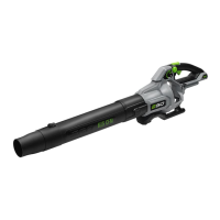
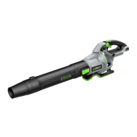
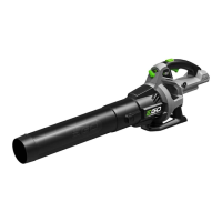
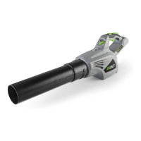
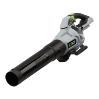
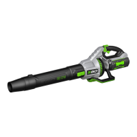
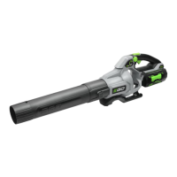
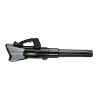
DESCRIPTION
KNOW YOUR BLOWER (Fig. A & B)
1. Handle
2. Battery-Release Button
3. Latch
4. Electric Contacts
5. Ejection Mechanism
6. Air Inlet
7. Middle Tube
8. Front Tube
9. Air Outlet
10. Control Handle
11. Adjustable Support Harness
12. Blower-Tube Storage Knob
13. Lock-off Lever
14. Boost Button
15. Variable-Speed Lever
16. Trigger
17. Wing Nut
18. Tube-Hanging Groove
WARNING: The safe use of this product requires an
understanding of the information on the tool and in this
instruction manual as well as knowledge of the project
you are attempting. Before use of this product, familiarize
yourself with all operating features and safety rules.
ASSEMBLY
WARNING: If any parts are damaged or missing,
do not operate this product until the parts are replaced.
Use of this product with damaged or missing parts could
result in serious personal injury.
WARNING: Do not attempt to modify this product
or create accessories not recommended for use with this
blower. Any such alteration or modication is misuse and
could result in a hazardous condition leading to possible
serious personal injury.
WARNING: To prevent accidental starting that could
cause serious personal injury, always remove the battery
pack from the tool when assembling parts.
ASSEMBLING THE BLOWER TUBES
1. There are two tubes for the blower: a front tube and a
middle tube (Fig. C).
2. First attach the front tube onto the middle tube. Align
either of the grooves in the front tube with the knob on
the middle tube (Fig. D).
3. Push the middle tube forward until the knob engages
either of the grooves. Then rotate the middle tube in
the direction of the arrow until the knob slides into the
lock position (Fig. E).
NOTICE: Before the middle tube is locked into place
during rotation, you will notice a built-in stop that will
create some resistance. Continue to rotate the tube past
the stop until it slides fully into the lock position.
4. You may shorten or lengthen the tube length according
to your preference by locking the middle tube into
different lock positions (Fig. F).
5. Attach the tube assembly onto the blower housing in
the same way (Fig. G).
6. To remove the tube assembly from the blower housing
or to separate the two tubes, rst turn the tube in the
unlocking direction to disengage the latch and then
pull the tube straight outward.