19
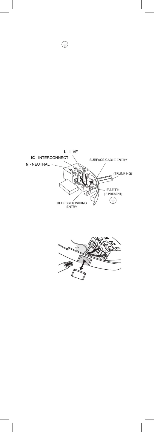
• check that the Interconnect wire is NOT connected to
Live, Neutral or Earth. Do not use an Earth wire for
the Interconnect line.
N.B. The Alarm does not need to be earthed. However
the terminal marked is provided for the convenience
of the installer so that any copper Earth wire or cable
coloured green & yellow, can be safely terminated.
To interconnect the Alarms connect all the IC terminals
together as shown in Figure 6.
4. If the mains wires are recessed, bring the wires
through the rear hole in the mounting plate as shown
in Figure 4.
If the mains wires are being brought along the surface:
(a) position the mounting plate so the cable trunking is
as shown in Figure 4.
(b) the mounting plate has a removable section, take it out
to interface directly with 25mm conduit as shown in Figure
5. If interfacing to 16mm conduit carefully cut around the
marked section, leaving the top intact and replace the
section. (If you are not using surface wiring, the removable
section must be left in place for electrical safety reasons).
There are two other positions which are also suitable for
the surface wiring to enter (and exit) the alarm, one next
to the removable section and another directly opposite.
5. Carefully align the mounting plate and screw into
place. Connect the wires to the terminal block. With
recessed wiring, ensure the rear gasket seals around the
edge of the hole in the ceiling or wall. This is to prevent
air draughts affecting the smoke/heat entering the
Alarm. If the hole is too large or the Alarm does not seal
it, it should be sealed with silicone rubber or equivalent.
6. Attach the battery to the battery snaps. Carefully line
up the unit on the base and slide on.
7. Press and hold the test/hush button for 10 seconds. The
horn will sound. On release of the test button the local alarm
will stop sounding immediately and the interconnected
Alarms will stop sounding a few seconds later.
8. Connect the mains power to the Alarm circuit. Check
the green light is on.
9. Attach the ‘Smoke Alarm’ identification label provided
to the distribution board to identify the alarm circuit.
10. Attach the ‘Mains Smoke / Heat Alarms’ label
provided on or near the distribution board and write in
date installed and the number of Alarms on the circuit.
REMOVEABLE
TRUNKING DOOR FOR
Figure 4
Figure 5