!
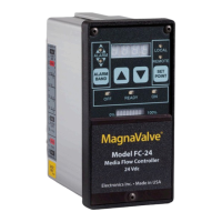
V!K!-.'1&,,!=*60+!PTKT@W!Q#1R!
This!is!the!0*0.5!Vac!process!input.!It!is!typically!n o t!u s ed !o n !t h e!F C *24!Controller.!
!
X!K!:&.3'!20+60+!PTKUT!Q/1R!!!
This! is! the! 0*10! Vdc! output.! The! Servo! Output! terminal! (8)! is! con nected! to! the! Analog! Input! of! the! attached!
MagnaValve!(orange!wire)!and!controls!the!flow!of!media!through!the!MagnaValve.!Zero!(0)!Vdc!commands!the!
MagnaValve!to!flow!0!lb/min!and!10!Vdc!commands!the!MagnaValve!to!flow!its!maximum!capability.!
!
Y!K!?*#$%&!20+60+!PLM!Q/1R!!!
•
When!the! mode! is!in! the! Ready! state! and! an! Enable! Input! signal!is!received,!an! Enable!Output!signal! is!
generated!at!terminal!#9.!
•
When!the!mode!is!in!the!On!state,!an!Enable!Output!signal!is!generated!at!terminal!#9.!
•
When!the!mode!is!in!the!Off!state,!no!Enable!Output!signal!is!generated!at!terminal!#9.!
The!Enable!Output!terminal!(9)!is!normally!connected!to!the!Enable!Input!wire!of!the!MagnaValve!(blue!wire).!!
!
UL!K!C%#.<!B&,&+!PLM!Q/1R!!
When!a!24! Vdc!signal!is!temporarily!applied! to!the!Alarm!Reset! terminal!(12),! all!alarms! will!be!reset.!If!a!constant!
24! Vdc! signal! is! applied! to! the! Alarm! Reset! terminal! (12),! the! alarms! will! be! held! in! the! reset! state,! essentia lly!
disabling!them.!
!
UZ!K!C%#.<!J4;O!!
The!Alarm!High!relay!contact!(13)!is!a!norm ally!o pen !relay !con tact.!T he!A larm !H igh !relay!c on tact!(13 )!w ill!close!if!
the!Process!Input!(6 )!is!high er!tha n !the!S etp oin t!valu e!(8)!p lus!th e!A larm !B an d !valu e!(4)!fo r!a!d ura tion !lon ger!th an !
the!Alarm!Delay!(17 ).!The !Servo !On *Off!(20)!must!be!on!for!alarms!to!wo rk. !
!
UM!K!C%#.<!)'<<'*!!
This!is!a!common!connection!to!all!relays.!
!
UW!K!C%#.<!A'5!
The!Alarm!Low!relay!contact!(15)!is!a!normally!open!relay!contact.!The!Alarm!Low!relay!contact!(15)!will!close!if!the!
Process!Input!(6)!is!lower! th an ! the ! Se tpo int!value!(8)! minus!the!A larm ! B and ! valu e! (4 )! fo r! a! duration!longer ! th a n !the!
Alarm!Delay!(17).!The!Servo!On*Off!(20)!must!be!on!for!alarms!to!work.!
!
US!K!7%'5!2[!!
The!Flow!OK! relay!contact!(16)!is!a! normally!open!relay!contact.!The!Flow! OK!relay!contact!(16)!will!close!if! the!
Process!Input!(6)!is!at!the!Setpoint!and!within!the!Alarm!Band!(4)!and!will!remain!closed!for!the !duration!of!th e!
blasting!/!peening!cycle.!If!the!Process!Inpu t! (6)!goes!higher!or!lower!than! the! Setpoin t! value! (8)!and!the!Alarm!
Band!value!(4)!goes!for!longer!than!th e! A larm ! D ela y! (17 ),!th e! Flo w !O K ! relay !c on ta ct!(1 6)! w ill!o p en !a n d! remain!open!
until!the! alarms! are!reset.!The!Servo!On*Off! (20)!m ust! be! on! for! any!of! the!alarms!to! work!(press!the!Servo!On* Off!
button!(20)!and!ensure!the!Servo!On!LED!(9)!is!lit).!
!
UX!K!B&1'./&.!20+60+!PTKUT!Q/1R!!
This!is!the!0*10!Vdc!analog!output.!The!Recorder!Output!terminal!(18)!is!typically!connected!to!a!PLC!or!some!other!
monitoring!equipment.!The!output!represents!the!flow!rate.! Zero!(0)!Vdc! represents!0!lb/min!flow!rate!and!10!Vd c!
represents!max im um!flow!rate.!
!
!
!