>4.4*;!
"&.<4*#%!:1O&<#+41!
!
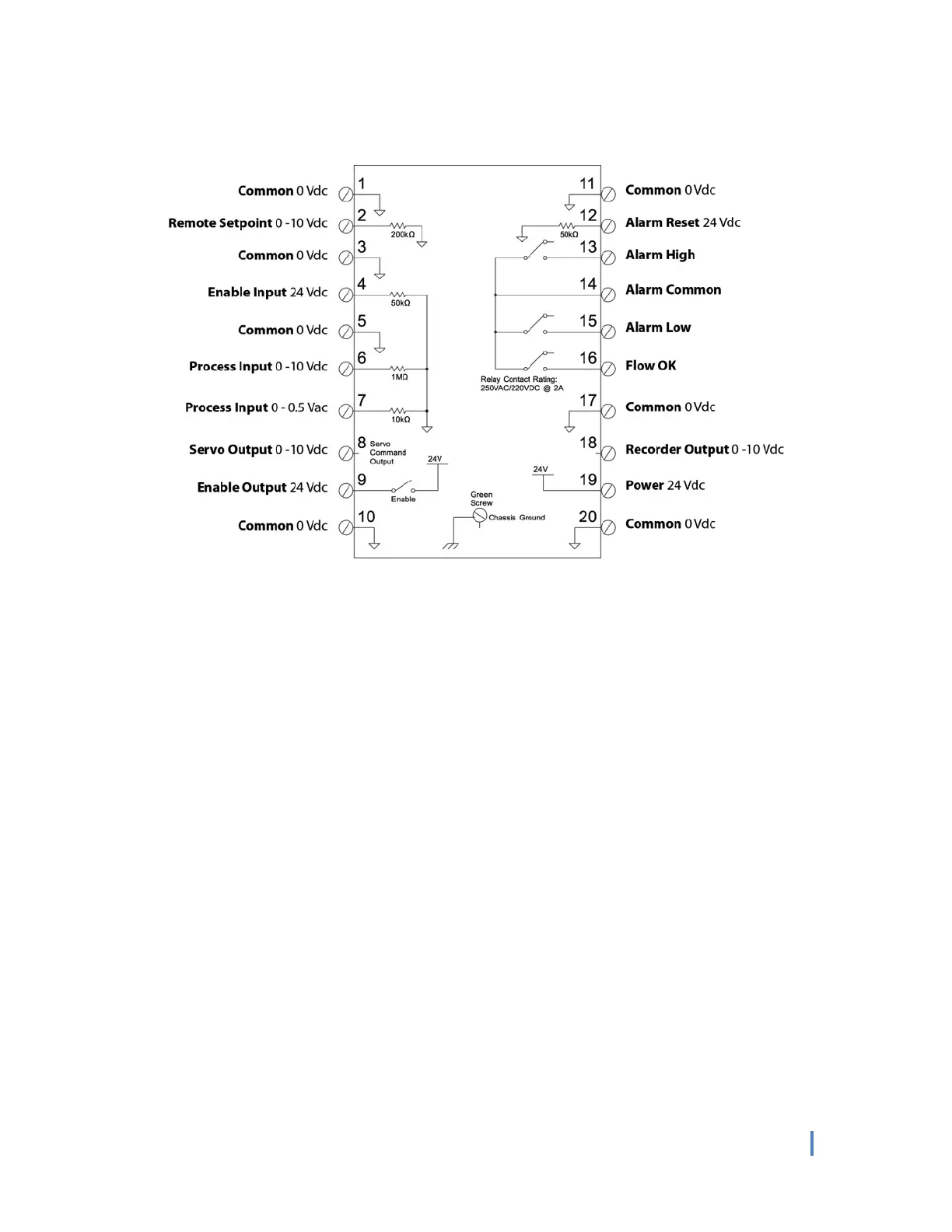
Note:!Refer!to!Operator!Control!Panel!and!Technical!Adjustment!Panel!diagrams!in!the!“Factory!Default!Settings”!
section!for!location!of!buttons!and!LEDs.!Refer!to!the!Terminal!Schematic!above!for!the!location!of!the!terminals.!
!
"&.<4*#%!9&,1.46+4'*,!
L!K!B&<'+&!:&+6'4*+!
Push! the!Setpoint!Local/Remote! button!(27)!until!Rem ote!Setpoint!LE D !(9)!is!on.!A pp ly!a!0*10!Vd c!analog!signal!to!
the!Remote! Setp oin t!term in al!(2 ).!A! zero !V dc!s igna l!w ill!corres po nd! to! a!0 % !flow!rate!command!and!a!10!V dc!signal!
will!correspond!to!a!100%!flow!rate!command.!To!display!the!Remote!Setpoint!command,!push!Setpo int!button!
(8).!The!Remo te!Se tpo int!c ommand!ma y!co m e !from !a !rem ote!pote ntiometer!or!any!other!0*10!Vdc!signal!source.!
!
M!K!?*#$%&!=*60+!PLM!Q/1R!
When!a!24!Vdc!signal!is!applied!to!the!Enable!Input!terminal!and!the!mode!is!in!the!Ready!state,!the!controller!will!
output! a! 24! Vdc! signal! on! the! Enable! Output! terminal! (9)! and! turn! the! M o de! Status! “On”! LED! (7).! The! Enable!
Output!terminal! (9)! is! normally!connected! to! the! Enable! Input! wire! of! the! Magna Valv e! (blue ! wire).! Th e! En able !
Input!sign a l!w ill!re s e t!a lar m s !th a t!o c cu r re d !d u rin g!t h e!la s t!c yc le .!
!
S!K!-.'1&,,!=*60+!PTKUT!Q/1R!
This!0*10! Vdc! process! input! represen ts! the! flow! rate! of! the! media! throu g h ! the! Mag naValve.! Zero! (0)! Vdc! input!
represents!0!lb/min !or!0!kg/min!and!10!Vdc!represents!the!maximum !calibrated!flow!rate!(see!Full!Scale!D isplay!
Range!under!Preliminary!Settings).!The!signal!is!displayed!on! the! Operator!Control! Panel’s!digital!display!(1).!When!
10!Vdc!is! applied,!the!FC*24!Controller!will!display!the!number!set!for!the!Display!Range!(28/29).!The! P rocess! Inp ut!
terminal!(6)!is!normally!co nnected !to!the!Analog!Output!of!the!Magn aValve!(white!wire).!
!
!