til
the
meter pointer
is
set
at
the
center
"
-0+"
.
The
range selector should
be
set
first to a position
at
least twice the
voltage
to be measured and then to
the lowest position which permits the meter pointer to remain on the
scale.
The
value
of
a positive
voltage
(deflection to the right
of
the
center
"-0+")
is
obtained
by subtracting
half
the range selector setting
from
the dc
voltage
reading on the
scale.
The
value
of a negative
voltage
(deflection to the left
of
the
center
"-0+")
is
obtained
by subtracting
thedc
voltage
reading on the
scale
from
half the range
selector
setting.
RESISTANCE
MEASUREMENT
Remove
all
power
from
the
equipment under test before making resistance
measurements
so
that
no vo I tages
are
present.
1.
Set the UNI-PROBE
at
"AC-OHMS" and the FUNCTION
selector
at
"OHMS".
2.
Set the RANGE
selector
at
"RX10".
3.
Short the UNI-PROBE to
the
Ground
Cable.
The
meter pointer should
be
at
the
left-hand
zero.
Use
the ZERO ADJ. control to reset
the
pointer
at
the
left-hand
"0
." , if necessary.
4.
Separate
the
UNI-PROBE
from
the'Ground
Cable.
The
meter pointer
should
be
at
the last
line
on the "OHMS"
scale.
Use
the OHMS ADJ. control
to reset the pointer
at
the
last line on the "OHMS"
scale,
if necessary.
5.
Connect
the
clip
on
the
Ground
Cable
to one terminal
of
the
resist-
ance
to be measured and touch the UN I-PROBE to the other terminal.
6.
Reset the RANGE
selector
to give a convenient deflection and mul-
Hply
the
reading on
the
"OHMS"
scale
by the factor indicated
at
the RANGE
selector
setting.
,I
Caution:
Meter
movements, thermocouples and other
low-current,
low-
resistance
d~vices
may be damaged unless a range above "RX10"
is
used. At
the
"RXI" and "RX10" positions, the instrument applies up to
1.5
volts to the
resistance under measurement. '
RESISTANCE
MEASUREMENT
ABOVE
1000 MEGOHMS
The upper limit
of
direct
resistance measurement with this instrument
is
1000 megohms.
The
leakage
resistance
of
small paper and mica capacitors
usually exceeds the
value.
To
measure resistance values above 1000 meg-
ohms, an external dc
voltage
source between 20 and 500 volts
can
be
used to
·4·
(
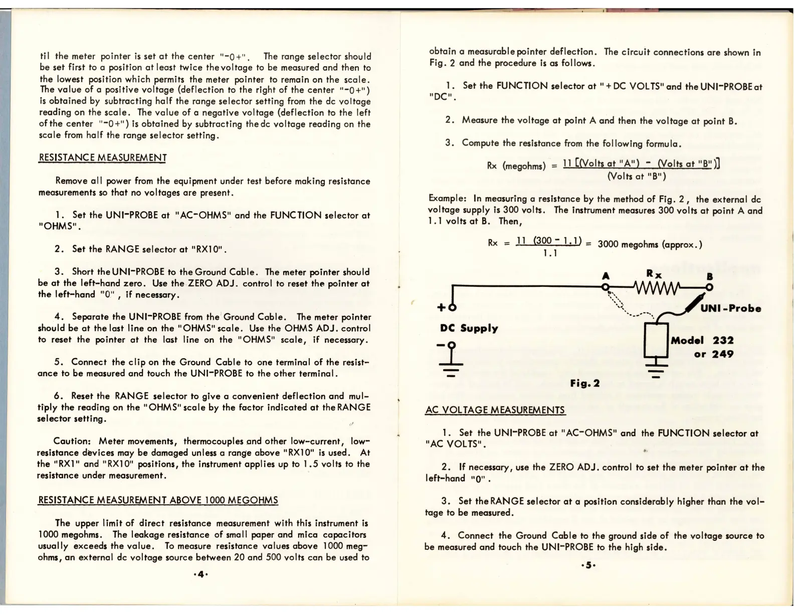
obtain
a measurable pointer
deflection.
The
circuit
connections
are
shown in
Fig.2
and
the
procedure
is
as follows.
1.
Set
the
FUNCTION
selector
at
II
+
DC
VOL TS"and the UNI-PROBE
at
"DC".
2.
Measure the
voltage
at
point A and then the
voltage
at
point
B.
3.
Compute
the
resistance
from
the
fo
lIowing formu
la.
Rx
(megohms) =
11
[(Volts
at
"A")
- (Volts
at
"B")]
(Volts
at
"B")
Example:
In
measuring a resistance by the method
of
Fig.
2,
the external dc
voltage
supply is 300 volts.
The
instrument measures 300 volts
at
point A and
1.1 volts
at
8.
Then,
Rx
=
11
(300 - 1
.1)
= 3000 megohms
(approx.)
1.1
A Rx
!
~-------------~
" .
+
"':\
.
..........
-
....
DC
Supply
B
o
or
249
Fig.2
AC
VOLTAGE
MEASUREMENTS
1.
Set
the
UNI-PROBE
at
"AC-OHMS" and the FUNCTION
selector
at
"AC VOLTS".
~
,
2.
If
necessary, use the ZERO ADJ. control to set
the
meter pointer
at
the
left-hand
"0".
3.
Set
the
RANGE
selector
at
a position considerably higher than
the
vol-
tage
to be measured.
4.
Connect
the
Ground
Cable
to the ground side
of
the
voltage
source to
be measured and touch the
UNI-PROBE to the high
side.
·5·
 Loading...