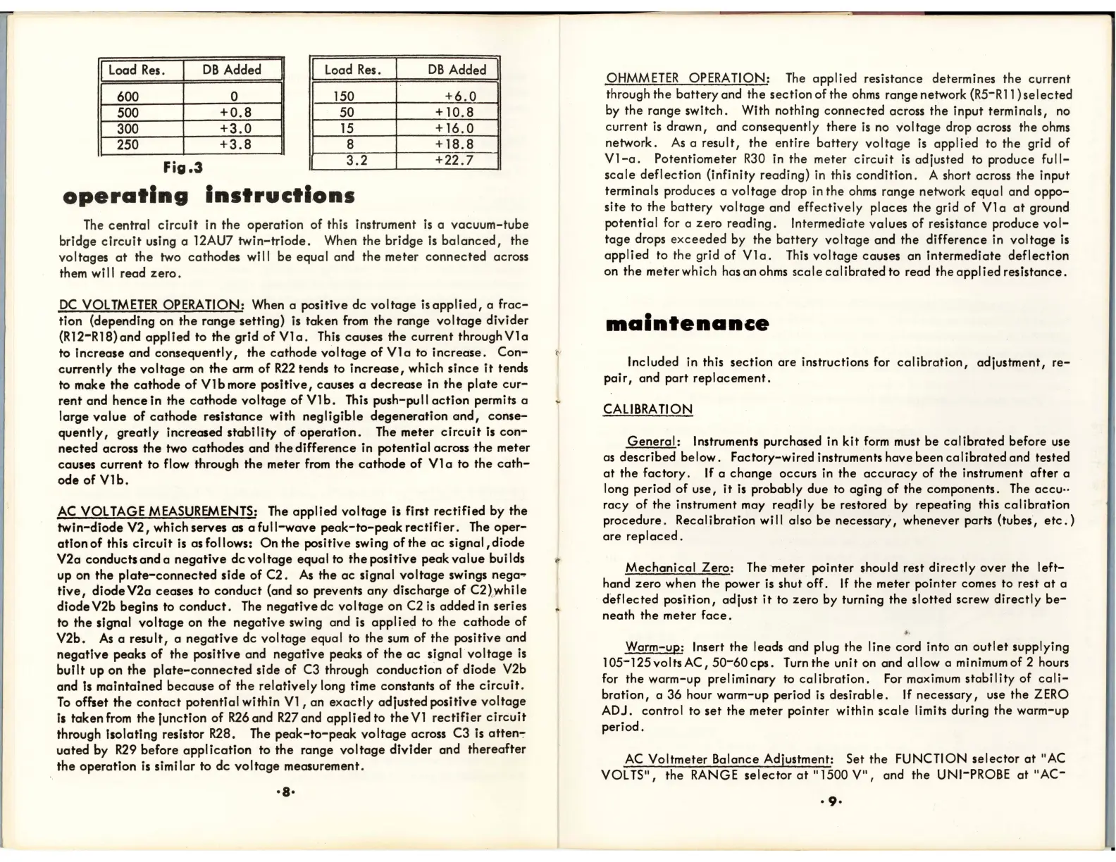
Load
Res.
DB
Added
I
Load Res.
I
DB
Added
I
600
0
150
+6.0
500
+O.S
50
+
10.S
300
+3.0
15
+16.0
250
+3.S
S
+IS.S
Fig.3
3.2
+22.7
operating
Instructions
The
central
circuit
in the operation of this instrument
is
a vacuum-tube
bridge
circuit
using a 12AU7
twin-triode.
When the bridge
Is
balanced,
the
voltages
at
the two cathodes will be equal and the meter connected across
them will read
zero
.
DC
VOLTMETER
OPERATION: When a positive dc
voltage
isapplied,
a
frac-
tion (depending on the range setting)
is
taken
from
the
range
voltage
divider
(RI2-RI8)and
applied
to
the
grid
of
VIa.
This
causes the current
throughVla
to Increase and consequently, the
cathode
voltage
of
VIa
to increase.
Con-
currently
the
voltage
on
the
arm
of
R22
tends to
increase,
which
since
it
tends
to make
the
cathode
of
VI b more positive, causes a
decrease
in
the
plate
cur-
rent
and hence in the
cathode
voltage
of
VI
b.
This
push-pull
action
permits a
large
value
of
cathode
resistance with negligible degeneration
and,
conse-
quently,
greatly increased
stability
of
operation.
The meter
circuit
is
con-
nected
across the two cathodes and the difference in potential across
the
meter
causes current to flow through the meter
from
the
cathode
of
VI a to the
cath-
odeofVlb.
AC
VOLTAGE
MEASUREMENTS:
The
applied
voltage
is first rectified by the
twin-diode
V2,
which serves as a
full-wave
peak-to-peakrectifier.
The
oper-
ation
of
this
circuit
is
as follows: On
the
positive swing
of
the
ac
signal,
diode
V2a conducts and a
negative
dcvoltage
equal to
the
positive peak
value
builds
up on
the
plate-connected
side of C2.
As
the
ac
signal
voltage
swings nega ..
tive,
diode V2a ceases to
conduct
(and so prevents any discharge
of
C2bvhi
Ie
diode V2b begins to
conduct.
The
negative dc
voltage
on C2
is
added in series
to the signal
voltage
on the
negative
swing and is
applied
to the
cathode
of
V2b.
As
a result, a
negative
dc
voltage
equal to the
sum
of the positive and
negative
peaks of the positive and negative peaks of
the
ac
signal
voltage
is
built
up on
the
plate-connected
side of
C3
through conduction
of
diode V2b
and
Is
maintained because
of
the
relatively
long time constants
of
the
circuit.
To
offset
the
contact
potential within
VI,
an
exactly
adjusted positive
voltage
is
taken
from
the
junction
of
R26
and
R27
and applied to
the
VI
rectifier
circuit
through isolating resistor R28.
The
peak-to-peak
voltage
across C3 is atten-:-
uated by
R29
before
application
to the range
voltage
divider
and thereafter
.
the
operation
is
similar to
dc
voltage
measurement.
'8·
OHMMETER
OPERATION:
The
applied resistance determines the current
through the battery and the section of the
ohms
range network
(R5-R
11) sel
ected
by the range switch. With nothing connected across the input terminals,
no
current
is
drown, and consequently there
is
no
voltage
drop across the
ohms
network.
As
a result,
the
entire battery
voltage
is
applied to the grid of
VI-a.
Potentiometer
R30
in
the meter
circuit
is
adjusted to produce
full-
scale
deflection (infinity reading)
in
this condition. A short across the input
terminals produces a
voltage
drop in the
ohms
range network equal and
oppo-
site to the battery
voltage
and effectively places the grid of
VIa
at
ground
potential for a zero
reading.
Intermediate values
of
resistance produce
vol-
tage
drops
exceeded
by the battery voltage and the difference in
voltage
is
applied
to the grid of
VIa.
This
voltage
causes an intermediate deflection
on the meterwhich hasanohms
scalecalibratedto
read the applied resistance.
lIIalntenance
Included in this section are instructions for cal
ibration,
adjustment,
re-
pair,
and port
replacement.
CALIBRA
liON
General:
Instruments purchased
in
kit
form
must be
calibrated
before use
as described below. Factory-wired instruments have been
ca
librated and tested
at
the factory.
If
a change occurs
in
the
accuracy
of the instrument
after
a
long period
of
use,
it
is
probably due
to
aging of the components.
The
accu··
racy of the instrument may rea,dily be restored by repeating this
calibration
procedure. Recal ibration wi
II
also be necessary, whenever parts (tubes,
etc.)
are
replaced.
Mechanical
Zero:
The
'meter pointer should rest
directly
over the
left-
hand zero when the power
is
shut off.
If
the meter pointer comes to rest
at
a
deflected
position, adjust
it
to zero by turning the slotted screw
directly
be-
neath the meter
face.
..
Warm-up: Insert the leads and plug the line cord into an
outlet
supplying
105-125voltsAC,50-60cps.
Turn
the unit on and allow a minimum of 2 hours
for the worm-up preliminary to
calibration.
For
maximum
stability
of
cali-
bration,
a 36 hour warm-up period
is
desirable. If necessary, use the
ZERO
ADJ. control to
set
the meter pointer within
scale
limits during the warm-up
period.
AC
Voltmeter Balance Adjustment: Set the FUNCTION selector
at
"AC
VOLTS",
the RANGE
selector
at
"1500
V",
and the UNI-PROBE
at
"AC-
•
9·
 Loading...