667 TUBE
TESTER
"
lEICQL,
»<
PAGE
17
"PLATE"
CONTROL
SETTING
20
40
60
80
“PLATE"
CONTROL
SETTING
NOTES:
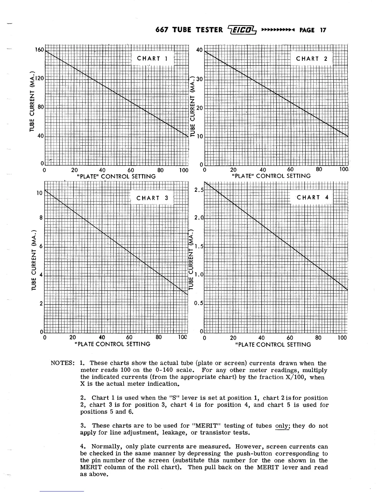
1.
These charts show the actual
tube (plate
or screen)
currents drawn
when
the
meter reads
100
on the
0-140
scale.
For
any other meter
readings, multiply
the
indicated
currents (from the appropriate chart)
by the
fraction
X/100,
when
X is the
actual
meter indication*
2.
Chart
1
is used when the "S" lever
is
set
at
position
1,
chart 2
is
for
position
2.
chart
3 is
for position
3,
chart 4
is
for
position
4,
and
chart
5 is used
for
positions 5 and
6.
3.
These charts are to
be
used for "MERIT" testing
of
tubes
only; they do not
apply for line adjustment, leakage, or transistor
tests.
4.
Normally, only plate
currents are measured. However, screen
currents
can
be checked in
the same
manner
by
depressing
the push-button
corresponding
to
the pin number of the screen (substitute this
number
for
the one shown
in
the
MERIT column
of the roll chart).
Then
pull
back
on the
MERIT lever
and read
as
above.