Do you have a question about the Eico 950B and is the answer not in the manual?
Instructions for carefully unpacking and checking the contents of the kit. Identifies parts and checks for damage.
Guidance on soldering techniques, tool usage, and lead trimming for proper assembly.
Step-by-step instructions for mounting binding posts, tube bracket, and potentiometers to the chassis.
Guidance on mounting the power transformer, terminal board, and inserting a grommet.
Connecting resistors and wires to the octal socket and other terminals as per diagram.
Detailed instructions for wiring various resistors, capacitors, and wires to the range switch.
Connecting power transformer leads, resistors, and capacitors to potentiometers and terminal boards.
Instructions for attaching the panel to the chassis, mounting the range switch, and inserting the tube.
Connecting component leads as illustrated in detailed wiring diagrams for specific ranges.
Checks for proper soldering, cleaning switches, and inserting the 6X5 tube.
Procedure for correctly aligning and attaching control knobs to potentiometers and switches.
Steps for initial power-on, checking filament and electron-ray tube glow, and calibrating the instrument.
Instructions for attaching rubber feet, handle, and mounting the completed unit into the cabinet.
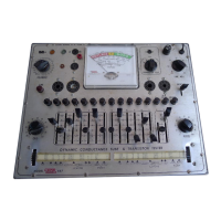
Overview of the Model 950-B's capabilities, features, and applications in electronic servicing.
Technical details including capacity, resistance ranges, comparator function, voltage, and physical dimensions.
Procedures for testing paper, mica, ceramic, and electrolytic capacitors for leakage.
Explanation of the bridge circuits, null indicator, and power supply operation.
Illustrations of bridge circuits for different range switch positions and leakage tests.
List of components available for replacement, including part numbers and descriptions.
General remarks and checks for proper operation, voltage variations, and component polarity.
Guidelines for troubleshooting, returning units for repair, and packing instructions.
| Brand | Eico |
|---|---|
| Model | 950B |
| Category | Test Equipment |
| Language | English |