Do you have a question about the Eico 667 and is the answer not in the manual?
Details updated steps for testing transistors, replacing old procedures.
Mentions specific text to be deleted from the instruction manual.
Instructs on revising existing text within the main manual.
Notes additions to components in specific figures on page 12.
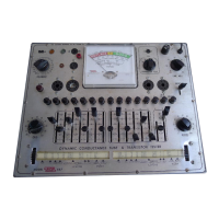
Introduces the EICO Model 667 as a tube and transistor tester with key advantages.
Specifies line voltage, frequency, and power consumption for the tester.
Lists the various types of tubes and transistors the instrument can test.
Outlines the types of tests performed on tubes and transistors.
Provides the size and weight of the EICO Model 667 tester.
Describes the Filament Selector and Line Adjust controls for voltage settings.
Explains the Grid and Plate controls for adjusting test parameters.
Details the function of Lever switches 1-12, C, and V for test setup.
Explains Lever S for sensitivity and push-buttons for element connections.
Describes the Transistor Test selector and H-K Leakage switch.
Outlines preliminary steps before conducting tube or transistor tests.
Continues the instructions specifically for performing tube tests.
Covers testing procedures, including twin triodes and leakage tests.
Guides on setting controls, inserting tubes, and warm-up.
Details performing line adjustment and evaluating leakage readings.
Provides acceptance criteria and preparation for MERIT tests.
Outlines steps for performing MERIT tests and completing tube tests.
Guides on finding transistor data and inserting the transistor for testing.
Explains test positions 1 and 2 and how to measure Beta.
Introduces the circuit description section and explains schematic symbols.
Explains the circuitry for inter-element leakage and line adjustment tests.
Details the functionality of the merit test circuit.
Describes the transistor test circuits, including Beta calculation.
Presents circuit diagrams for various leakage tests.
Shows schematics for line adjustment and merit tests of pentodes/triodes.
Displays schematics for merit tests of duo-triodes, diodes, and rectifiers.
Shows schematics for VR tubes and transistor tests.
Step-by-step guide for removing the instrument from its cabinet.
General instructions for performing internal adjustments.
Details calibration, socket cleaning, and fuse replacement procedures.
Explains the mechanical operation of the roll chart assembly.
Step-by-step guide for installing a new roll chart.
Instructions on how to enter interim test data into the roll chart.
Outlines the general steps for determining test settings for new tubes.
Details how to set lever switches for various tube elements.
Covers inserting tubes and performing line adjustments for new tubes.
Provides guidance on setting PLATE and GRID controls for merit tests.
Explains how to interpret and use the provided tube charts.
Displays Charts 1-4 showing tube current relative to plate control settings.
Presents Chart 5 and procedures for power rectifier merit tests.
Details procedures for setting up merit tests for light-duty diodes.
Provides detailed steps for merit testing of diodes.
Covers procedures for testing dual tubes and full-wave rectifiers.
Lists electronic components, switches, and various tube sockets with stock numbers.
Lists hardware items like nuts, screws, and washers.
Lists mechanical parts like brackets, gears, and includes manuals.
Schematics for transistor tests, filament selection, and overall test circuits.
Circuit diagrams illustrating leakage and merit test operations.
Outlines EICO's policy on parts replacement and repair services.
Provides guidelines for safely shipping units for service.
Details the terms and conditions of the EICO warranty.
Lists the minimum fees for labor and handling of repairs.
Lists authorized warranty service agencies by state across several regions.
Continues listing authorized service agencies by state and includes Canadian locations.
| Type | Tube Tester |
|---|---|
| Manufacturer | Eico |
| Model | 667 |
| Tube Sockets | 9-pin miniature, 7-pin miniature, octal, loctal |
| Weight | Approx. 10 lbs |
| Power Supply | 105-125 VAC, 50-60 Hz |