PAGE 8
«««««««<
^BiCQln
667
TUBE
TESTER
The functioning of
the Model
.667
in
each
of the various
tests furnished
is as
follows:
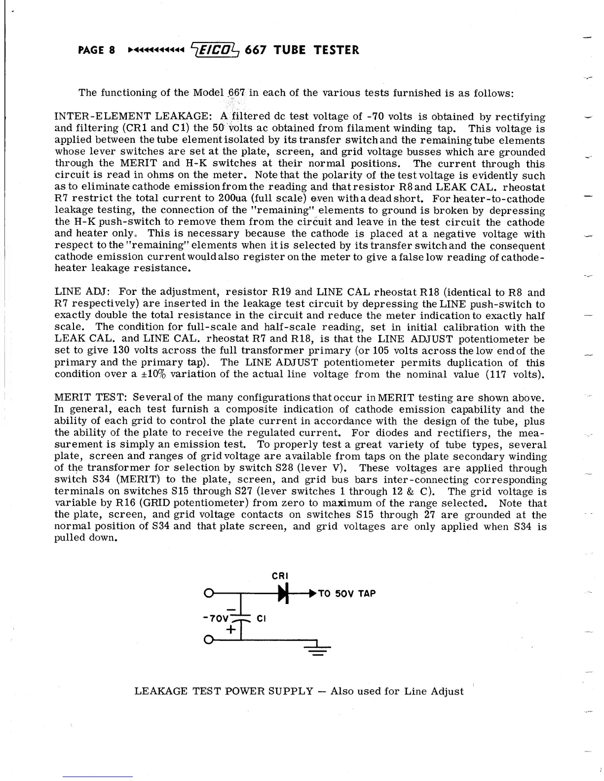
INTER-ELEMENT LEAKAGE:
A
filtered dc
test voltage
of
-70
volts
is
obtained
by
rectifying
and filtering
(CR1
and
Cl)
the 50 volts
ac obtained
from
filament
winding
tap. This
voltage
is
applied between the
tube
element
isolated
by
its
transfer
switch and
the
remaining
tube
elements
whose
lever switches are set at the
plate, screen,
and
grid
voltage
busses
which are
grounded
through
the MERIT and H-K
switches at
their normal
positions.
The
current
through
this
circuit is
read
in
ohms on the meter.
Note that
the polarity
of the test
voltage
is
evidently
such
as
to
eliminate cathode
emission from the
reading
and
that resistor
R8and
LEAK
CAL.
rheostat
R7 restrict the total current
to
200ua (full scale)
even
with
a
dead
short. For
heater-to-cathode
leakage
testing, the connection
of the "remaining"
elements
to ground
is
broken
by
depressing
the H-K push-switch to remove
them
from the
circuit and
leave
in
the test
circuit
the cathode
and heater only.
This
is necessary
because
the
cathode
is placed
at
a negative
voltage
with
respect to the
"remaining" elements
when
it is
selected
by its transfer
switch and
the
consequent
cathode emission
current
would
also
register
on the meter to
give
a false
low reading
of
cathode-
heater
leakage resistance.
LINE ADJ: For the adjustment,
resistor
R19
and
LINE CAL
rheostat
R18 (identical to
R8 and
R7
respectively)
are inserted
in the
leakage
test circuit
by depressing the
LINE
push-switch
to
exactly double
the total resistance
in
the circuit and
reduce
the
meter
indication
to exactly
half
scale.
The condition
for full-scale and
half-scale
reading,
set
in initial
calibration
with
the
LEAK
CAL. and LINE
CAL.
rheostat
R7
and
R
18,
is
that the
LINE
ADJUST potentiometer
be
set to give 130
volts
across the
full transformer primary
(or
105
volts
across
the low end
of the
primary and the primary tap). The
LINE
ADJUST
potentiometer
permits
duplication
of this
condition
over a
±10%
variation
of the
actual line voltage
from
the nominal value
(117
volts).
MERIT
TEST: Several
of
the many
configurations that
occur in MERIT
testing
are shown above.
In
general,
each test furnish
a
composite indication
of
cathode
emission
capability and
the
ability of each
grid
to control the plate
current
in accordance
with
the design of the
tube, plus
the ability of the
plate
to receive
the regulated
current.
For diodes and
rectifiers,
the mea-
surement
is simply an emission test.
To properly
test a
great variety
of
tube types, several
plate, screen
and
ranges
of grid
voltage
are available
from taps
on
the
plate secondary
winding
of
the
transformer for
selection
by
switch
S28 (lever
V). These
voltages
are applied
through
switch S34 (MERIT) to the plate,
screen,
and grid
bus bars inter
-connecting
corresponding
terminals
on switches S15 through S27 (lever
switches
1 through
12
& C).
The grid
voltage
is
variable
by R16
(GRID
potentiometer)
from zero
to maximum
of the range selected.
Note that
the plate, screen, and grid
voltage
contacts on
switches
S15
through 27
are grounded at
the
normal
position of S34 and
that plate
screen, and grid
voltages
are only
applied
when S34
is
pulled down.
o
"70V~
+
O
—
-
ci
TO
50V
TAP
LEAKAGE TEST
POWER SUPPLY
-
Also
used for Line
Adjust
 Loading...