PAGE
2
««««<«
‘
lEICQL,
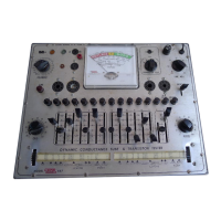
667
TUBE
TESTER
FUNCTIONS
OF
CONTROLS
A
necessary
supplement to
the operating
instructions
is the following
description
of
control
functions. Several
controls,
for example,
have
unusual
secondary
functions
which
must
be
understood in making settings.
FILAMENT SELECTOR
—
The
dial
of this control
indicates
rms
a-c volts
tapped from
the
power transformer and
applied
to the tube
filament
at each
position.
Do
not take
the setting
for
granted;
check the roll chart
and
set it to the
value
shown for the
particular
tube type.
The
last position, marked "Z",
is
used
when checking
cold
cathode
tubes
such astheOZ4
for
which
the
plate voltage
of the
Model
667
is
insufficient
to
initiate
conduction
in
the tube.
The
117 volts
available
from the FILAMENT switch
is thrown
in series
with
the plate
voltage
of 180 volts
at
the "Z"
position to provide
a total voltage
sufficient to
initiate
tube
conduction.
A
3K resistor,
placed in
series with this circuit,
provides
current
limiting to
protect
the
tube
after the start
of conduction.
LINE ADJ.
—
This
control
is a continuously
variable potentiometer
connected
across
a portion
of the primary winding.
It permits adjustment
of
transformer
secondary
voltages
to the stand-
ard test
values
despite
line voltage
and filament
load
variations.
The LINE
push-button serves
to insert
a
standard
resistance in the leakage
test circuit
which will
result
in exactly
half-scale
deflection (LINE mark)
when
the LINE ADJ.
control
has been
set
properly
in relation
to the
actual line voltage and
filament load.
The actual
line voltage
may
be
read
off the
dial
of the
LINE ADJ. control
with an accuracy
of
±3%
when
line adjustment
is
made
under
no-load
condi-
tions (no
tube
inserted for testing).
GRID
control
—
A
continuously
variable
potentiometer
which
taps the desired grid
voltage
up
to a maximum of
5,
15,
or 45 volts,
depending
on the setting
of the V lever. A
snap
switch,
which takes
up
the first
few divisions on
the dial,
is
actuated
in the most
counter-clockwise
position and inserts
a
400S2
current-
limiting resistor
in
series with the
plate
supply (for high-
current
rectifiers). At settings
of 7
and
above, the
resistor
is shorted.
PLATE control
--
A
continuously
variable rheostat
in series with the
meter which
acts as
a
"fine"
adjustment
of meter sensitivity
in conjunction
with the
"coarse"
adjustment provided
by
the
"S"
lever
switch.
LEVER switches 1 through 12
&
C
--
These
are single section
six-position
switches
which
con-
nect the similarly numbered
tube socket
terminals (lever
C is
for
the
cap lead) to the
proper
voltage sources for the tube which
is
to
be
tested.
At
the
1
position,
each switch
contacts
ground; at the
2
position, each
switch contacts the filament
voltage;
at the
3
position, each
switch
contacts the screen
voltage;
at the
4
position,
each
switch contacts plate
voltage;
in the
5
position, each
switch
contacts grid
voltage;
in the
6
position,
each
switch furnishes an open
circuit.
LEVER
V
-
This is a three section switch
with four
positions
(1
through
4).
5,
15,
45,
90 and
180
volt
taps
on a separate secondary winding
on the transformer are
so connected to these
switch sections as to provide selection
from
four combinations
of plate,
screen, and grid
voltages.
The
plate
and
screen
voltages selected
are applied
through the
MERIT
switch to the
corresponding
position contacts
on lever switches 1
through
C.
The grid
voltage selected
is
applied
to
the
GRID
potentiometer so that the
desired
portion of the total
available voltage
can
be accurately tapped
off
by
means
of
the
dial calibration and
applied to
the
grid
position contacts
on
lever
switches 1
through
C,
also
through the
MERIT
switch. The plate
screen, and grid
voltages selected
at each position of the V
switch
are
as
follows:
 Loading...