r
electrical
installation
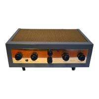
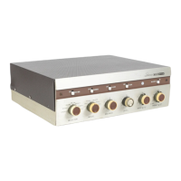
GENERAL
a) INPUTS: There are identical
pairs of
MAG. PHONO,
TAPE
HEAD,
MICROPHONE,
AUXILIARY
A,
and
AUX-
ILIARY B inputs—
oneof each pair
in channel land
chan-
nel
2 —and
each Is identified
accordingly by the suffix
1 or 2.
The MAG. PHONO,
TAPE HEAD,
and MICRO-
PHONE
pairs of inputs
are
all
"low
level" Inputs, mew-
ing that
they all feed
through a
preamplifier/equalizer
stage
In either channel
1 or 2. The
AUXILIARY
A «id
AUXILIARYB pairs of
inputs are
"high level" inputs,
mean-
ing that they enter
either channel
1 or 2 at
a point after
the preamplifier/equalizer
stages.
The
AM, PM and FM-
FM Multiplex
inputs are
also "high level
inputs",
which
are
internally selected
in pain— one for
each
channel
-by the
SELECTOR
switch. At the
TUNER,
AUX, posi-
tion
of
theMODEswitch,AMonly
is selected
at the
AM-
FM position of
the SELECTOR
switch,
and FM only
Is
selected
at the FM-FM
MULTI, position
of the
SELECTOR
switch.
1)
MAG. PHONO
1,
MAG. PHONO 2:
These inputs
are intended for
the two outputs ofa
stereo
magnetic cart-
ridge,
or
for
a stereo ceramic
cortridge with
ode^tors.
Four-terminal cartridges
(each sensing
element brought
out
to a separate
pairof terminals)are
generally
advantageous
as
compared to
three-terminal cartridges
(one terminal
of
each sensing
element brought
out to a common
terminal)
because
the possibility of
Increased
hum
due to
a
ground
loop can be avoided.
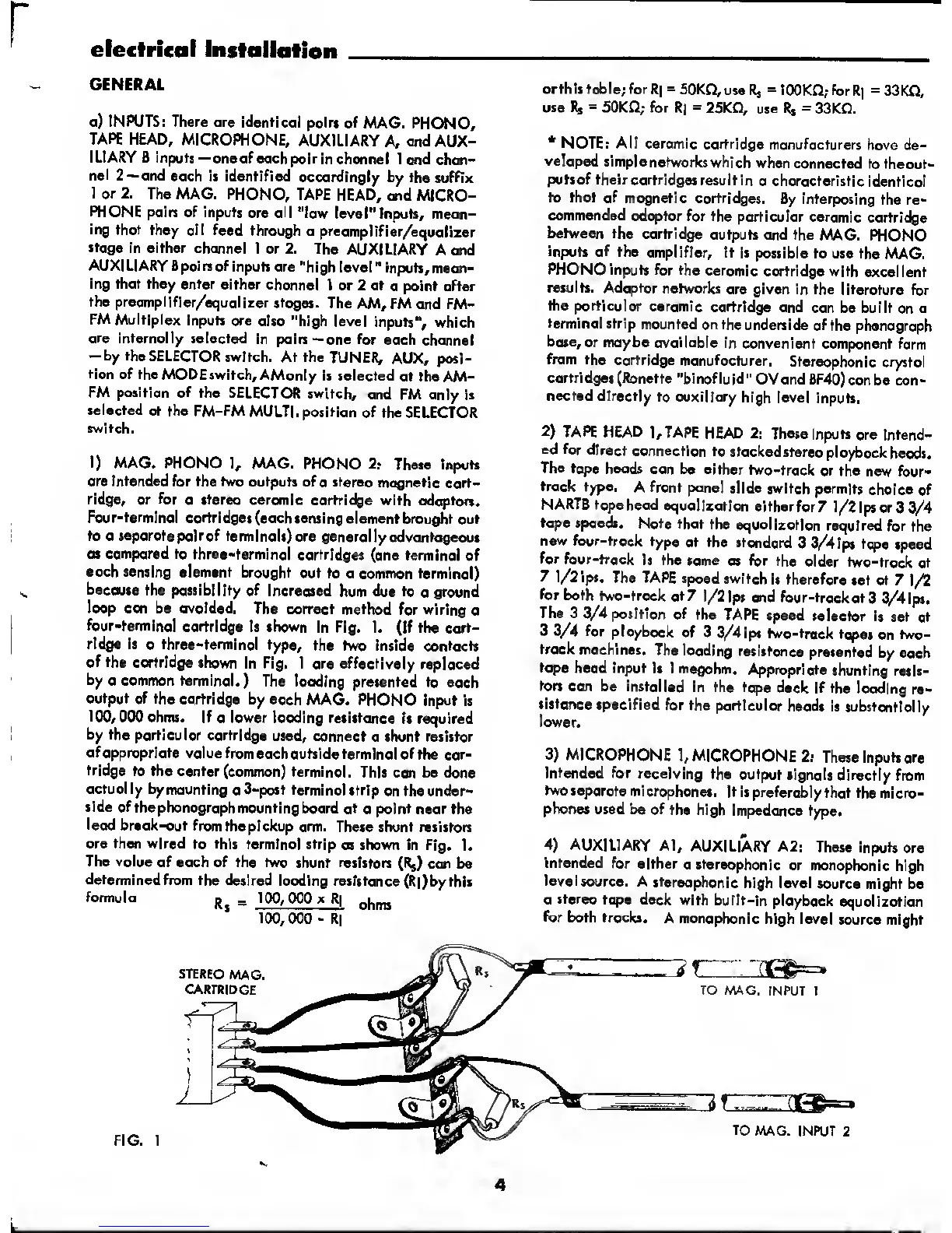
The correct method
for wiring
o
four-terminal cartridge
it shown
In Fig. I. (If the cart-
ridge is
a three-terminal type, the
two Inside contacts
of the
cartridge shown
in Fig. 1 ore effectively
replaced
by
0 common terminal.)
The loodlng
presented to each
output of the cartridge
by each
MAG. PHONO
Input Is
100, 000 ohms. If
a
lower loading
resistance
is required
by the
particular cartridge
used, connect
o shunt resistor
ofopproprlote
voluefromeochoutside
terminal of
the car-
tridge
to the center
(common) terminal.
This can be done
actually by
mounting
a
3-post terminal
strip on the
under-
side of
the phonograph mounting
boord ot
a
point
neor the
lead
break-out fromthepickup
arm. These
shunt resistors
ore then wired
to
this
terminal strip
os shown in Fig.
1.
The value
of each of the two
shunt resistors
(Rj) ccm be
determined
from the desired
loading resistance
(R|)bythls
formula
_
100, 000 x R|
*
100,
000
-R|
orthi5table;forR|
=
50K£5,u$eRs
=
lOOKfi; for
R]
=33KQ,
use Rj
=
50KG; for
R|
=
25Ka
use
R*
=
33Kfl.
*
NOTE: All ceromic cartridge
manufacturers
hove de-
veloped
simple
networks which
when connected
to the
out-
puts of their cartridges
result in
a characteristic
identical
to that of
magnetic cartridges.
By interposing
the re-
commended
adaptor for the
porticulor ceramic
cartridge
between the
cartridge
outputs and the
MAG. PHONO
inputs of
the
amplifier. It Is
possible to use the
MAG.
PHONO Inputs
for
the
ceramic
cartridge with
excellent
results. Adaptor
networks
ore given in the literature
for
the particular
ceramic
cartridge and
can be built
on
a
terminal
strip
mounted on the
underside of
the phonograph
base,
or maybe available
in convenient
component
form
from the
cartridge manufacturer.
Stereophonic crystal
cartridges (Ronette
"binofluid"
OVand BF40)
can be con-
nected directly to
auxiliary
high level Inputs.
2)
TAPE HEAD
],TAPE
HEAD 2: These
inputs
are intend-
ed for
direct
connection
to
stackedstereoploybockheods.
The tape
heads can
be either
two-track
or the new four-
track type.
A front panel
slide switch
permits
choice of
NARTB tope head
equalization
eitherfor?
l/2ipsor3
3/4
tope
speeds.
Note
that
the
equalization required
for the
new
four-trock
type at
the stondard
3 3/4 ips
tope
speed
for
four-trock 1$
the same as
for the
older
two-track at
7
l/2ips.
The TAPE speed
switch
Is therefore
set ot 7
1/2
for
both
two-trock at7
1/2 Ips ond four-trock
at3
3/4lps.
The 3
3/4
position of
the
TAPE speed
selector is
set at
3
3/4 for ployback
of 3
3/4ips two-track
tq}es
on
two-
trock
machines.
The loading
resistance
presented
by each
tope
heod input
is 1 megohm.
Appropriate
shunting resis-
tors
can be
Installed
In the tape
deck if the
loading
re-
sistance
specified
for the
particular
heads is substantially
lower.
3)
MICROPHONE
1,
MICROPHONE
2:
These inputs ore
Intended
for receiving
the output
signals directly
from
two separate
microphones.
It ispreferably
that themicro-
phones used be of
the high
impedonce type.
4)
AUXILIARY Al,
AUXILIARY A2:
These inputs
are
Intended
for either
a stereophonic
or monophonic
high
level
source. A
stereophonic
high level
source might be
a
stereo tape
deck
with built-in
playback
equalization
for both tracks.
A monophonic
high level
source might
4
 Loading...