ST40
ive
and unmusica I*
Some people
prefer not
to use loud-
ness
compensation
at
al
I, because
it does
not correspond
to
any
natural
listening
condition at a
live performance*
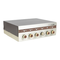
BAS$CONTROLCH.1,BASSCONTROLCH.
2
(CON-
CENTRIC): The plus
sign on the right side
of the dial
Indicates that
clockwise rotation
from
the mid-point
(0)
of either control
Increases
(boosts)
bass
response;
the minus sign on the left
side indicates
that counter-
clockwise rotation from
the
mid-point decreases
(cuts)
bass response. There
is
no
interaction
with the TREBLE
control*
Start
all adjustments
with this
control set
at
the
mid-pofnt
(0),
which is called
the “flat" position
since
bass
response
Is neither cut
nor boosted at
this
position.
TREBLE CONTROL
CH.
1,
TREBLE
CONTROL
CH.2
(CONCENTRIC):
The plus sign
on the
right side
of
the
dial
indicates
that clockwise rotation
from the mid-
point
(0)
of
either
control increases
(boosts) treble
re-
sponse;
the minus sign indicates
that
counter-clockwise
rotation from
the mid-point
decreases
(cuts) treble re-
sponse. There
is no interaction
with the BASS
control.
Start
all
adjustments
with
this control set at
the mid-
point
(0),
which is called the "flat"
position
since
treble
response Is neither
cut nor boosted
at this posi-
tion*
The amplifier
ON-OFF power switch is ganged
with
the CH.2 TREBLE control*
Note the
word “OFF" on
the panel
|
ust beyond full
-counter-clockwise
rotation*
The plain circle symbol preceding
it indicates
that the
power switch
is ganged
with
the
CH. 2 control.
Turn
the
amplifier
off by turning the
CH.2 TREBLE control
beyond full
counter-clockwise rotation
until the power
switch
clicks to OFF* Turn the amplifier
on
by
turning
the
CH.2 TREBLE
control
clockwise
from
OFFand set-
ting
it
at the
mid-point
(0)
or some customary
setting
^
of
the
CH. 2 TREBLE control
you may use.
LO
FILTER
slide switch: Set to
ON when
it
Is desired
to
cut low
frequency response below
100 cps because
of
rumble
in a phonograph
or even in
broadcast
program
material.
Phonograph
rumble Is
usually at about
29
cps and
may well not
be
directly audible. Sometimes
it can
be
at
a
much lower
frequency,
which
is
defin-
itely
not directly
audible* However, the
effect of
rumble
can
be
heard
even the rumble itself Is
not*
It
manifests
itself
by
using up
amplifier
power at low
frequencies
and
can
even
overload the
amplifier*
If,
at
normal
listening levels
on
phonograph,
setting the
LO
FILTER
to ON
definitely
results
In "cleaner", less-
distorted
sound, the
indication
isthatyour
phonograph
PAGE
9
suffers
from excessive
rumble. Whether
it
is worth
doing
anything about
it,
depends
on
the installation,
if
you have
Inexpensive speaker
systems that
do not
produce substantial undi
started
sound below
80
cycles,
you mayjustas well
live
with the rumble and
eliminate
its bad effects by
using the
LO
FILTER.
If you
have
made
a considerable
investment
in speakers, partly
In.
order to obtain full,
undistorfed
response
below
80
cycles,
you
may not
want to forego
full bass
response.
In the latter cases,
have
the phonograph
examined
by
a
qualified
service man to see
If the
rumble is
caused
by a
defect that can be
remedied.
HI FILTER slide
switch: Set to
ON when
it Is desired
to
cut
high frequency response
above 5000
cps.
Use-
ful
for
minimizing extraneous
noise when
listening
to
narrow
range AM
broadcasting,
for listening
to
noisy
or worn
records,
and for reducing
the
annoyance of
excessive
distortion
from any
source.
TAPE
MONITOR slide
switch: Useful
with complete
tape
machines
(including
record and playback
elec-
tronics) that
provide
off-the-tape
monitoring
facilities
while recording.
In this situation,
setting
the TAPE
MONITOR slide
switch to
ON permits you
to hear
the
program
being
recorded directly
from the
tape.
MAINTENANCE
INSTALLATION
PROCEDURES
FOR
MINIMUM
HUM
AC
LINE CORDS:
Hum can
usually
be
reduced
by the
following
procedure, after all
the equipment
used
with
the amplifier
is connected
to It and plugged
in.
1. Turn on all
the equipment
used*
2. Reverse
the amplifier's
AC
line cord
plug In the wall
outlet
to
see
If
hum is
reduced. Leave
it in the
position
that results
in
least
hum.
3* With
the
SELECTOR
switch,
select a
particular
piece of
equipment,
and determine
the insertion
posi-
tion of
its AC
line
cord plug
that
results
in
least
hum.
4.
Repeat
step
3 for
every piece
of
equipment used
with
the amplifier.
When
this
is
done,
proceed to HUM BALANCE
adjust-
ments.
 Loading...