EasyManua.ls Logo

eicos FH12B02-M12 - User Manual

eicos FH12B02-M12
2 pages
Print Icon
To Next Page IconTo Next Page
Loading...
40m20m
L2
A1
A2
A1+
A2-
+
+
R
Reed Switch Reed Switch
2K2 - 2W
D = 20 ~ 40m
22R 5W
R
220R 5W
{
Manual
C.01/Oct2018

Models for G 1/2” Port
FH Series
eicos.net
 |  | 
IMPORTANT !
YOU MUST CHECK BEFORE INSTALLATION

AC Current: Use K8
*
Filter in parallel with the coil (A1 A2) of a contactor or relay.
DC Current: Use KD
*
Filter in parallel with the coil (A1 A2) of a contactor or relay.
*
For sale on accessories.eicos.us
Direct connection
to the sensor
Use 22R 5W
*
resistor in series
Use
24Vdc Voltage


Use mini contactor or auxiliary relay.
ELECTRONIC EQUIPMENT:
Use 4K7 10W resistor.
 Use 220R 5W
*
resistor.

 
Operation






 require prior testing. Use
lter before the Sensor to prevent the internal piston from locking. Not
recommended for industrial water waste.
      require technical
analysis: the Sensor contains magnetic components inside. Use a
magnetic lter before the Sensor to avoid deposition/settling that will
prejudice its operation.
The sensors work in all voltage and current ranges displayed in the table bellow:
Operating Voltage   Peak Current
110Vac 20VA 0,2A 0,5A @20ms
220Vac 20VA 0,1A 0,5A @20ms
5Vdc 2,5W 0,5A 1A @20ms
12Vdc 5W 0,5A 1A @20ms
24Vdc 10W 0,5A 1A @20ms
 NOT recommended

On datasheets.eicos.us available technical specications

02 (two) years warranty.

All Sensors have been tested and approved during the manufacture process.

K8 Snubber Filter for
electrical installation (AC)
(included)

Filter
Installing the snubber lter extends the
lifespan of the sensor’s electrical contact.
*
On accessories.eicos.us check models and prices of Filters
 - Attention to Install
Note: Reed Switches have reached over one million operations in tests with
contactor and K8* snubber lter.

Reed Switches are hermetically sealed contacts
actuated by a magnetic eld.
The life expectancy of a reed switch refers to a
kind of load to be used. Reed Switches of the highest reliability are applied in
our sensors, and their life expectancy can reach above two million operations.
However, when they are switching lamps, inductive or capacitive loads, this
number may decrease.

It is important to consider that the power specied by an electrical load is
often referred to the permanent working state.
For higher power, use an auxiliary relay or contactor as recommended below,
or similar.
This resistor dampens the peak voltage caused by the
capacitance of cables and electronic equipment input.
due to CAPACITANCE, which
can occur depending on the distance and cable used in the connection to the contactor.
K8
*
Filter mounted in
parallel with the coil of an
AC contactor, increases the
contact life.
• Switching inductive loads
0.1µF 400V


• Connecting the sensor to a contactor in long distances, use resistor:
• Connecting the sensor to an electronic equipment:
Important: For installation with , use 4K7 10W resistor.
•Timing relay
•Frequency inverter
•Etc.
Flow Switches and Level Switches for liquids
KD
*
Filter mounted in
parallel with the coil of a
DC relay, increases the
contact life.
BY448
or
1N4007
Important: For distances , use 24Vdc voltage.
K8*
K8*
KD*





Initial: 31.7VA
Rated: 5.1VA
Contactor
Contactor
K8 for AC
KD for DC
Question and Answer IconNeed help?

Do you have a question about the eicos FH12B02-M12 and is the answer not in the manual?

Summary

Operation and Liquid Handling

Handling Fouling Liquids

Handle liquids with solid particles/fouling by testing first and using a filter to prevent piston locking.

Handling Magnetic Particle Liquids

Liquids with ferrous/magnetic particles require analysis due to magnetic components; use a magnetic filter.

Electrical Connection and Protection

Important Installation Checks

Crucial checks must be performed before installation to ensure proper operation and longevity.

Sensor Protection for Extended Life

Follow specific instructions for auxiliary contactors, solenoid valves, power contactors, and electronic equipment.

Reed Switch Electrical Contact

Understand reed switch operation, switching power considerations, and use of auxiliary relays for higher loads.

Reed Switch Performance Enhancement

Implement protection procedures like using K8/KD filters for inductive loads and resistors for capacitance risks.

Sensor Specifications and Installation

Technical Specifications Overview

Details material, clearance, pressure, temperature, port, sealing, output, enclosure, and contact specifications.

Installation Guidelines

Install in applications without excessive vibration, maintaining minimum distance from ferrous surfaces.

Sealing and Thread Compatibility

Information on O-ring sealing and GAS (BSP) thread compatibility, advising against sealant tape.

Flow Rate Sensitivity Adjustment

Instructions on how to adjust the sensor's sensitivity using an Allen wrench for flow rate settings.

Mounting Dimensions

Provides dimensional information for mounting the sensor, including correct and incorrect orientations.

Electrical Connection (A-coding)

Details the M12 male plug (2 pins) connection for the flow switch.

Sensor Maintenance

Steps for cleaning the sensor plug, spring, and testing the electrical contact with an ohmmeter.

Overview

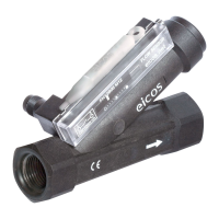
This document describes the Eicos FH Series Flow Switches, designed for G 1/2" port applications. These devices are crucial for detecting the presence and flow of mediums, triggering an electrical contact based on the precise displacement of a magnetic piston.

Function Description

The core function of the FH Series Flow Switches is to detect fluid flow. When fluid passes through the sensor, it causes a magnetic piston to move. This movement, in turn, actuates a hermetically sealed reed switch, which serves as the electrical contact. This mechanism allows the sensor to signal the presence or absence of flow. The reed switch is a highly reliable component, designed for millions of operations, ensuring longevity and consistent performance. However, it's important to note that the lifespan can be affected by the type of load being switched; inductive or capacitive loads may reduce its operational life. The sensors are designed to operate across a range of voltages and currents, with specified maximum switching power and current. They are particularly sensitive to flow rate, and their sensitivity can be adjusted to suit specific application requirements.

Usage Features

The FH Series Flow Switches are designed for straightforward installation and reliable operation in various industrial settings.

Installation:

  • Mounting: The sensors should be mounted with a parallel port connection and an O'Ring for proper sealing. It's crucial to maintain a minimum distance of 20mm from any ferrous surface to prevent interference. The installation should also avoid areas with excessive vibration to ensure accurate readings and prolong the sensor's life.
  • Sealing: The device comes with an NBR O'Ring for effective sealing, eliminating the need for additional sealant tape or overtightening during installation.
  • Electrical Connection: The sensor utilizes an M12 male plug with 2 pins for output connection. An M12 female connector is not included but is required for connection.
  • Protection for Electrical Contact: To protect and extend the lifespan of the reed switch, specific precautions are recommended:
    • Auxiliary Contactor: For direct connection to a solenoid valve or power contactor, using a mini contactor or auxiliary relay is advised. If connecting directly to the sensor over distances of 20m to 40m, a 22R 5W resistor in series is recommended. For distances greater than 40m, 24Vdc voltage should be used.
    • Electronic Equipment: When connecting to electronic equipment such as interface relays, relay couplers, timing relays, or frequency inverters, specific resistors are recommended. For interface relays/relay couplers, a 4K7 10W resistor is needed. For timing relays and frequency inverters, a 220R 5W resistor is suggested.
    • Inductive Loads: To improve reed switch performance when switching inductive loads, an K8 filter (for AC current) or KD filter (for DC current) should be mounted in parallel with the coil of the contactor or relay. These filters help increase contact life.
    • Capacitance Risk: There is a risk of reed switch contact welding due to capacitance, which can occur depending on the distance and cable used in the connection to the contactor. Using a resistor when connecting the sensor over long distances (20m-40m) helps dampen peak voltage caused by cable capacitance and electronic equipment input.
  • Fluid Compatibility: While suitable for various mediums, prior testing is required for liquids with solid particles or fouling to prevent the internal piston from locking. A filter should be used in such cases. For liquids with ferrous or magnetic particles, technical analysis is needed, and a magnetic filter should be used to prevent deposition that could hinder operation. The sensors are not recommended for industrial wastewater.
  • Sensitivity Adjustment: The flow rate sensitivity of the sensor can be adjusted using an Allen wrench, which is included. This allows users to fine-tune the sensor's response to specific flow conditions.

Maintenance Features

Maintaining the FH Series Flow Switches is straightforward, focusing on cleanliness and verifying electrical contact.

  • Cleaning: If encrustation occurs, the sensor can be easily cleaned. This involves opening the plug, removing the spring, and cleaning the internal components with a brush.
  • Reassembly: After cleaning, the sensor should be reassembled as illustrated in the manual, ensuring all components are correctly seated.
  • Testing Electrical Contact: To verify proper function after cleaning or during troubleshooting, the electrical contact can be tested using an ohmmeter. This involves moving the magnetic piston and observing the ohmmeter reading to confirm the reed switch is actuating correctly.

These features collectively ensure that the FH Series Flow Switches are not only effective in their primary function of flow detection but also user-friendly in terms of installation, protection, and ongoing maintenance, contributing to their long-term reliability in diverse applications.

eicos FH12B02-M12 Specifications

General IconGeneral
ModelFH12B02-M12
Sensing Distance2 mm
Protection RatingIP67
Output TypePNP
Voltage Range10-30V DC
Housing MaterialBrass, nickel-plated
Operating Temperature-25°C to +70°C
Connection TypeM12 Connector
TypeInductive sensor