Do you have a question about the EINHELL BT-UP 470 and is the answer not in the manual?
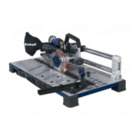
This document describes the Einhell BT-UP 470 Universal Panel Saw, an electric tool designed for precise cutting of wood and panels. The manual provides comprehensive instructions for assembly, operation, maintenance, and safety, ensuring users can operate the device effectively and safely.
The Einhell BT-UP 470 Universal Panel Saw is primarily designed for slitting and cross-cutting of timbers and panels. It is equipped with a carbide-tipped saw blade, ensuring clean and accurate cuts. The device is intended for use with suitable saw blades made of HM or CV materials, strictly prohibiting the use of HSS saw blades or cutting-off wheels. This tool is not suitable for cutting any type of round wood.
The saw features an ON/OFF switch (1) for easy control, a safety lever (2) to enhance operational safety, and a handle (3) for comfortable grip and maneuverability. A knurled handle (4) is provided for locking the motor unit in splitting position, which also releases the safety lever. The workpiece clamping device (5) secures the material during cutting, preventing movement and ensuring precision. Guide rails (6) facilitate smooth and accurate movement of the saw unit.
For angle adjustments, the saw includes an angle stop (10) and a locking screw (8) for the angle stop, allowing for precise angle settings from -10° to +45°. A saw blade position indicator (9) helps in aligning the blade correctly. The machine table (12) provides a stable surface for the workpiece, and a table insert (13) supports the material directly around the saw blade. The saw blade guard (16) and saw blade cover (17) offer protection during operation, while the extractor socket (15) allows for connection to a dust extraction system to maintain a clean working environment.
The parallel stop (23) with its locking screw (24) is crucial for making longitudinal cuts, ensuring the workpiece is guided straight and parallel to the saw blade. A push stick (11) is supplied and stored in a holder, to be used for safely guiding narrow workpieces through the saw blade. The device also includes a spindle lock (19) for securing the saw blade during changes, and a saw blade screw (20) with a washer (21) and outer flange (22) for mounting the saw blade (14). A dust bag (not illustrated) can be attached to the extractor socket for dust collection.
The panel saw is equipped with an overload cut-out switch that disconnects the power supply if the saw blade is jammed or blocked, preventing damage to the motor. This switch automatically unlocks after a certain period, allowing the device to be reset.
Before initial use, users must read and follow all operating instructions and safety information. The assembly process involves inserting plastic feet (7) into the housing corners and securing them with supplied screws, springs, and washers. The handle (3) is also attached using screws.
For optimal performance and safety, the table insert (13) should be changed if it becomes worn or damaged. Changing the saw blade (14) requires pulling out the power plug and wearing work gloves. The knurled handle (4) is used to lock the equipment at the guide rail (6). The screw from the saw blade cover (17) is unscrewed, and the spindle lock (19) is pressed while turning the saw blade screw (20) anticlockwise with the hexagon wrench (18) to remove the blade, washer, and outer flange. The new saw blade is then fitted in reverse order, ensuring the correct cutting direction of the teeth, which should point upwards. All safety devices must be properly mounted and in good working condition before resuming operation.
When making longitudinal cuts, the motor unit is locked in the splitting position using the knurled handle (4), which releases the safety lever. The parallel stop (23) is set to the desired width and locked with its screw (24). The workpiece clamping device (5) and angle stop (10) are removed to allow the workpiece to lie flat on the table. The device should be switched on, and the blade allowed to reach full operating speed before pushing the workpiece through under the saw blade cover (16). For narrow workpieces (smaller than 120 mm in width), a push stick (11) must be used. For very narrow workpieces (30 mm or less), a push block (a) is required (not supplied). It is crucial to push the workpiece through to the end of the splitter and leave offcuts on the saw table until the blade has stopped.
For cross cuts and angle cuts (-10° to +45°), the parallel stop (23) is removed. The angle stop (10) is set to the required angle and secured with the workpiece clamping device (5). Angles can be set in one-degree increments from -10° to 10° using the locking screw (8). For angles like 15°, 20°, 30°, and 45°, the locking screw (8) is removed, the angle stop (10) repositioned, and the workpiece clamping device (5) inserted into the hole on the angle stop to fasten it. The workpiece is secured with the clamping device (5). After switching on the equipment and allowing it to reach full speed, the safety lever (2) is pressed to raise the saw blade cover (16), and the equipment is pulled through the workpiece by its handle. The equipment is then pushed back until the workpiece is released. The workpiece and sawdust should only be removed after the saw blade has stopped moving.
Regular maintenance is essential for the longevity and safe operation of the Einhell BT-UP 470. Before any cleaning or maintenance work, the mains power plug must always be pulled out.
All safety devices, air vents, and the motor housing should be kept free of dirt and dust. This can be achieved by wiping the equipment with a clean cloth or blowing it down with compressed air at low pressure. It is recommended to clean the equipment immediately after each use. The appliance should be cleaned regularly with a damp cloth and some soft soap, avoiding aggressive cleaning agents or solvents that could damage the plastic parts. Care must be taken to prevent water from entering the interior of the equipment.
The guide rails (6) and plastic bearings require regular cleaning after each use. If necessary, a little oil should be applied to the guide rails (6) to prevent them from rusting, ensuring smooth movement of the saw unit.
For servicing, dust and dirt should be removed regularly from the equipment, preferably with a fine brush or cloth. Caustic agents should never be used to clean plastic parts. The saw unit drag device should be kept clean and lubricated at regular intervals.
In case the power cable is damaged, it must be replaced by the manufacturer, its after-sales service, or similarly trained personnel to avoid danger. When ordering replacement parts, specific information such as the model/type, article number, ID number of the equipment, and the spare part number of the required component must be provided.
The equipment is supplied in packaging designed for transit protection, and the raw materials of this packaging can be reused or recycled. Defective components of the equipment, made of various materials like metal and plastic, must be disposed of as special waste, following local council guidelines. Electric tools should never be placed in household refuse; advice on correct disposal should be sought from local waste authorities.
| Mains supply | 230 V ~ 50 Hz |
|---|---|
| Power | 470 W |
| Max. immersion depth | 5 m |
| Max. water temperature | 35 °C |
| Power cable | 10 m |