EKO INSTRUMENTS CO., LTD. - Pyranometers MS-802/802F/402/402F/602 - Instruction Manual Ver.13
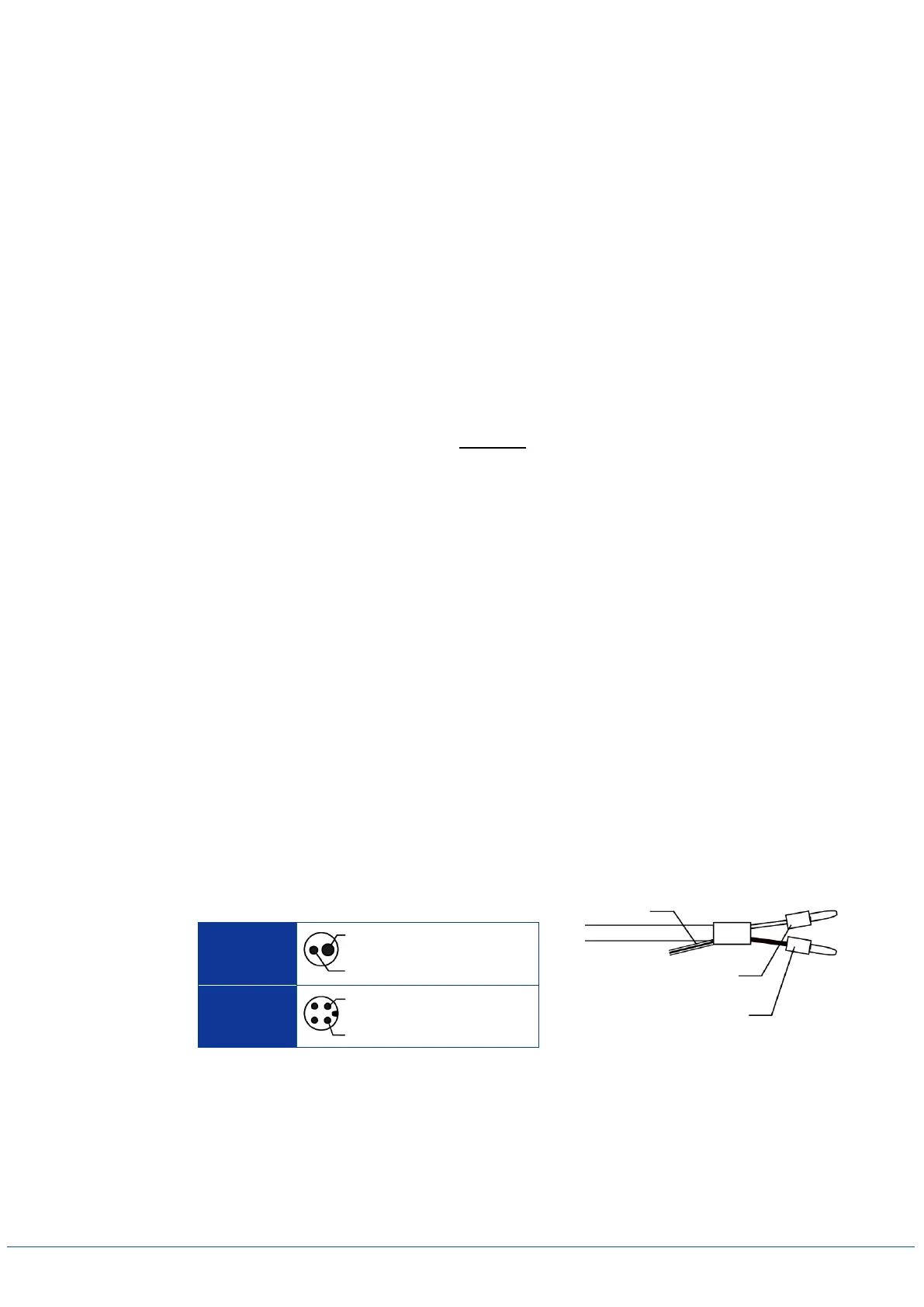
Figure 5-2. Cable Connection
White Wire (+) Plus Output
Black Wire (-) Minus Output
5) If the pyranometer is not leveled properly, the pyranometer readings are affected by cosine and
azimuth errors. Periodically check the spirit level and adjust the pyranometer’s position if necessary.
If the pyranometer has to be installed in a tilted-angle mounting position then proceed in two steps
as follows:
First, place the pyranometer on a flat installation base which is in a truly horizontal position then
adjust the instrument’s leveling screws by observing the air bubble in the spirit level while
manipulating the leveling screws; the instrument is leveled horizontally if the air bubble is in the
center ring.
Second, mount the pyranometer with the adjusted leveling screws in the desired tilted position.
*When installing the instrument, do not remove the leveling screws; if the leveling screws are
removed, it may cause abnormal output values due to the thermal effects from the mounting part.
6) Fasten the pyranometer to the base with the 2 bolts (included) and put the sun screen back on the
pyranometer. (Always turn the sun screen clockwise).
2. Wiring
1) To extend the cable life time, make sure that the cables are not exposed to direct sun light or
rain/wind by lining the cable through a cable conduit. Cable vibrations will potentially cause noise in
the output signal. Fasten the cable so that the cable does not swing or move by wind blowing.
Exposure of the signal cable to excessive electromagnetic emissions can cause noise in the output
signal as well. Therefore the cable should be lined at a safe distance from a potential source
generating EM noise, such as an AC power supply, high voltage lines or telecom antenna.
2) Connect the output cable to the pyranometer.
Make sure to check the pin layout of the connector before connecting the cable. If the connector
cannot be easily inserted, DO NOT use any force as it will damage the connector. Visually check the
pin layout again before retrying to insert the connector.
3) Connect the other end of the output cable to the signal tester or data logger as follow:
Table 5-3. Output Cable Pin Layout
4) Check the output voltage.
If a large noise is seen in the output voltage signal, try to connect the shield to (-) minus input
terminal.
*Connecting shield cable does not mean the noise will be removed, thus make sure to keep away
from possible source of noise when wiring.
(+) Plus Output (White Wire)
(-) Minus Output (Black Wire)
(+) Plus Output (White Wire)
(-) Minus Output (Black Wire)
 Loading...