Do you have a question about the ELABO G7-1G and is the answer not in the manual?
Details on device variants and optional features that enhance performance range.
Guidance on using the manual for familiarization, correct, cost-effective, and safe operation.
Explanation of common abbreviations and symbols used in the manual.
Overview of tester types (G7-1G, G7-1T) and their modular design and capabilities.
List of standards the device supports for testing.
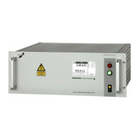
Information about the device's name plate and its location.
General safety guidelines, operator qualifications, and precautions for safe use of the tester.
Explanation of safety symbols and danger zone markings.
Guidelines on intended use, modifications, and ELABO's liability exclusion.
Rules for safe operation, malfunction handling, and managerial responsibilities.
Procedures for checking and using safety features and emergency stop functions.
Requirements for operator training, instruction, and responsibilities.
Warnings and safety measures related to high voltage testing up to 5000V AC.
Safety procedures for discharging test objects with internal capacitance due to stored charge.
Instructions for safe transport, unpacking, and installation of the tester.
Permitted operating environments regarding dust, flammability, humidity, and temperature.
Guidance on securely installing the device in a housing or rack.
Principles of connecting the tester via a connection box for HV testing.
Information on connecting the device to the mains supply, including fuse protection.
Methods of operation (stand-alone, rack, manual, external control) and safety circuit requirements.
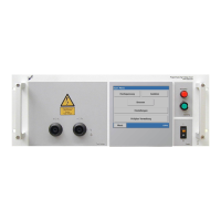
Overview and operation of the touchscreen interface.
Procedure for powering on the device, including prerequisite checks and boot sequence.
Overview of device states and operating modes (front panel, DA interface, RS232/Ethernet/USB).
Information on the two safety circuits and their function for enhancing safety.
Overview of operating modes (PE, HV, IS) with their respective voltages and currents.
Diagram illustrating the choice between Fast-Start and Normal modes for test sequences.
Flowchart detailing the steps involved in a Normal-Mode test sequence.
Detailed flowchart for the HV/IS test within Normal Mode.
Detailed flowchart for the PE-test within Normal Mode.
Flowchart detailing the steps for executing a Fast-Start-Mode test sequence.
Flowchart for the combined PE-HV-ISO test sequence in Fast-Start-Mode.
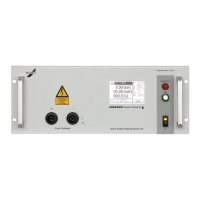
Details on high voltage power connections (X2, X3, X12) and their functions.
Description of connections for PE conductor measurement (X10, X11).
Information on various interfaces like Ethernet, USB, RS232, and Service interface.
Description of the standard Ethernet interface for control and firmware updates.
Information on the optional RS232 interface and its pin assignments.
Details on the 25-pin digital interface X7 for safety circuits and external control.
Explanation of how to achieve a 'High' signal on digital inputs and voltage requirements.
Overview of the expanded interface with digital and analog I/O capabilities.
Pin assignment and function of the 7-pole Krönes high voltage connector X3.
Pin assignment and function of the connector for the PE-test probe.
Information on operating the tester with a test cabinet and its connection.
Details on connecting warning lamps for high voltage tests.
Information on using safety test probes for manual testing.
Procedure for replacing fuses, including type and safety precautions.
Instructions for cleaning the device housing.
Instructions for cleaning the touchscreen display.
Detailed technical specifications for different device variants (G1-1G, G1-1T, G1-1H, G1-1U).
General technical data for DC devices, including connections and memory.
Overview of the touchscreen menu system and how it operates.
Display of the main menu options: Manual test, Parameter set, Test plans, Device settings.
Procedure for performing manual tests, including password entry and parameter display.
Overview of creating and editing parameter sets.
Overview of managing test plans and performing automatic tests.
Procedure for starting and executing automatic tests.
Procedure for handling faults during automatic tests, including repeating steps or aborting.
Procedure for setting device parameters and operating parameters via the setup menu.
Settings for high voltage tests, including test mode, voltage range, and run-up.
Settings for insulation resistance tests, including test mode, voltage, and run-up.
Parameters for protective earth conductor (PE) tests according to relevant standards.
Parameters for the Burn test option, used for locating insulation faults.
Procedure for inserting time steps to interrupt test sequences.
Method for calculating idle time during HV/ISO tests with and without ramp-up.
Base settings for digital and analog inputs/outputs, including naming and scaling.
Procedure for defining self-explanatory names for digital outputs/inputs.
Procedure for defining self-explanatory names, units, and final values for analog outputs/inputs.
Details on the additional digital interface with 6 digital outputs.
Information on the expanded interface with 16 digital outputs, 8 digital inputs, 2 analog outputs, 3 analog inputs.
Procedure for creating parameter blocks for inputs/outputs.
Setting digital output states (on/off) for controlling relays or digital inputs.
Configuring analog outputs for generating nominal values or control signals.
Using digital inputs for monitoring switches or digital outputs.
Configuring analog inputs for monitoring values and setting limit values.
Procedure for creating test plans by inserting input/output parameter blocks.
Procedure for loading and executing test plans in manual or automatic mode.
How to start automatic test plan execution.
Procedure for reading digital input states and checking against settings.
Procedure for reading analog input values and checking against limits.
Procedure for setting digital output states defined in the parameter set.
Procedure for setting analog output states and voltage values.
Procedure for starting test steps manually in step mode.
Procedure for updating firmware using the Flash programmer.
Function for reading and displaying stored test results.
Function for scanning COM ports and establishing connection with ELABO devices.
Conditions and prerequisites for using the Fast-Start Mode effectively.
Limitations and restrictions applicable when using the fast-start mode.
| Brand | ELABO |
|---|---|
| Model | G7-1G |
| Category | Test Equipment |
| Language | English |