Do you have a question about the Elan EM78P458 and is the answer not in the manual?
Describes the operational registers used within the microcontroller.
Details the R3 Status Register, its bits, and functions.
Details the R9 ADCON register for analog-to-digital conversion control.
Details the RF Interrupt Status Register and its flags.
Introduces special-purpose registers, including the Accumulator.
Describes the Accumulator (A) register for data transfer and operand holding.
Details the CONT Control Register, its bits, and functions.
Explains the TCC/WDT prescaler functionality and circuit diagram.
Describes the bi-directional I/O ports (Port 5, Port 6) and their control registers.
Details the events that initiate RESET and the subsequent device behavior.
Describes the ADC circuitry, control registers, and functional block diagram.
Provides an overview of the PWM functionality and output.
Introduces the Timer1 and Timer2 functionality.
Describes the TMRX block diagram and signals.
Guides on programming registers related to TMRX and PWMX.
Explains the external reference signal for the comparator.
Details the comparator outputs and their adjustment.
Explains how to use the comparator as an operation amplifier.
Describes the interrupt mechanism for the comparator.
Explains how the comparator can wake the device from SLEEP mode.
Lists the four oscillator modes (HXT, LXT, ERC, IC).
Explains how to use crystals or ceramic resonators with the OSCI pin.
Describes the External RC Oscillator mode and its frequency characteristics.
Explains the RC Oscillator mode with an internal capacitor.
Details an external RC circuit for generating a reset pulse.
Explains how to build a residue-voltage protection circuit.
Details the bits and functions of the Code Option Register (Word 0).
Details the bits and functions of the Code Option Register (Word 1).
Shows the AC test input/output waveform and measurement points.
Depicts the reset timing diagram.
Illustrates the TCC input timing diagram.
Lists the AC electrical characteristics of the microcontroller.
Details the A/D converter characteristics.
Lists the comparator characteristics.
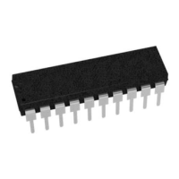
Lists the available package types for the microcontrollers.
| Architecture | 8-bit |
|---|---|
| Program Memory | 4KB |
| Operating Voltage | 2.5V ~ 5.5V |
| Timers | 2 |
| Operating Temperature | -40°C to +85°C |
| RAM | 128 bytes |