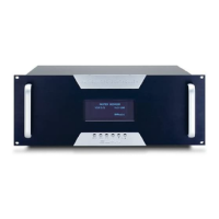
Do you have a question about the Elan System12 and is the answer not in the manual?
Connections for audio, video, and local sources into the S12.
Connections for audio and video distribution to amplifiers and displays.
Ports for keypads, IR, RS-232, triggers, and system expansion.
Wiring diagram for connecting VIA! Touch Panels to the PS12 Precision Panel.
Details connecting ELAN electronic volume controls, simplifying integration with the PVSE Precision Panel.
Connects S12 Zone Keypad Inputs to PS12's RJ-45 jacks for keypads, touch panels, and IR receivers.
Connects PS12 Local Source RJ-45 jacks to S12's corresponding inputs for zone-specific sources.
Details connecting VIA! Touch Panels to the PS12 for power using 16VDC/4A or 16VDC/10A supplies.
Connects 3.5mm stereo cables from PS12 front panel to S12 Sense Trigger Inputs.
Details connecting VIA! Touch Panels directly to the S12 using PVIA Wall Plates.
Shows how to connect ELAN keypads directly to the S12 without a PS12.
Connects local audio sources to the S12 via LSWP Wall Plates and Cat-5 cable.
Details connections for electronic volume controls directly to the S12, Z-600, and amplifier.
Connects ELANSense sensors directly to the S12's Sense Trigger Inputs.
Facilitates connections for telephone, page, doorbell, and override signals to the Z-600 Controller.
Details connecting the PZ600 to the S12 for doorbell and paging functions.
Connects Z-600 PAGE & DB OUT to S12 PAGE IN and S12 MOH OUT to Z-600 MOH IN.
Allows volume control via IR or serial commands at preamp level for flexible system configuration.
Deliver line-level audio at full output (100% volume) for sub-zone volume control.
Allows sending a Fixed and a Variable output simultaneously for sub-zone advantage.
Details RS-232 and IR/RS-485 connectivity between the SS1 and S12 using specific cables.
Shows how to connect the VIA!SC4 System Controller to the S12 via RS-232 serial cable.
The default audio/video switching mode; first 12 video inputs track audio inputs.
Routes up to 5 Composite and 1 Component video output to a zone with a single command.
Explains how Component video signals (Y, PB, PR) are switched and grouped for routing.
Allows switching both Component and Composite video simultaneously using matrix capabilities.
Details the default Composite video zone outputs for VIA! Touch Panels and TVs.
Explains how Component video outputs are grouped and routed to TVs or monitors.
Allows routing any of 16 video inputs to any of 16 outputs, requiring extensive programming.
Allows routing Composite and Component video simultaneously to specific zones.
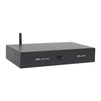
| Zones | 12 |
|---|---|
| Type | Controller |
| Display | LCD |
| Connectivity | RS-232, IR |
| Remote Control | Yes |
| Operating Temperature | 0°C to 40°C |