ELAN RS-232 Serial Port Connections
VIA!
®
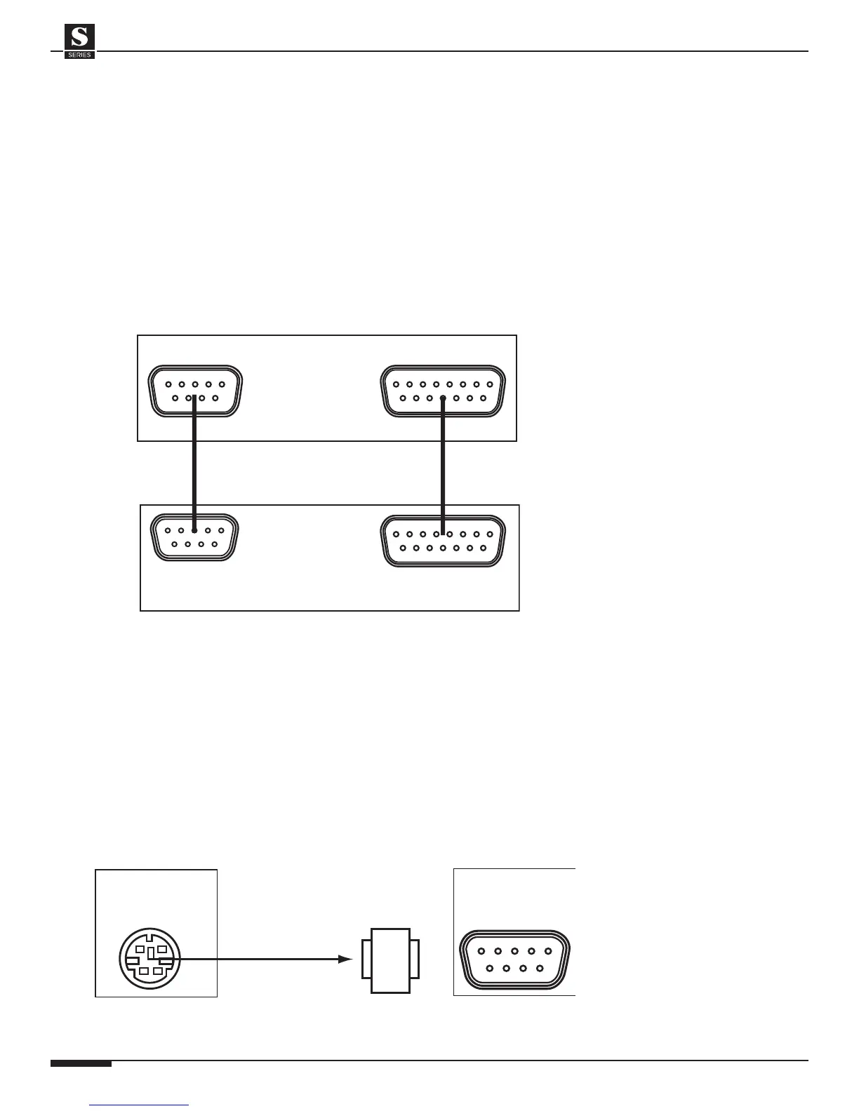
2-SS1 to S12 Connections
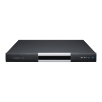
The VIA!2-SS1 System Station allows many advanced features in an S12 system.
Wireless VIA! Touch Panels can communicate with the S12 and other sub-systems
through RS-232 or IR. Connectivity between the SS1 and the S12 is done through
two cables (included with the SS1); a 15-pin cable for IR and RS-485, and a 9-pin
cable for RS-232. Connect these cables as shown below. Please consult the
VIA!2-SS1 Installation Manual for important information regarding the use of this
product.
VIA!
®
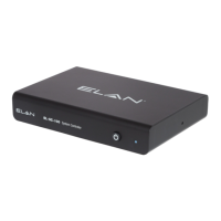
SC4 to S12 Connections
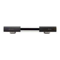
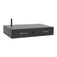
When controlling a System12 with ELAN’s VIA!SC4 System Controller, use the
6-Pin DIN-to-9-Pin serial cable and the male-to-male DB9 gender-changer that is
included with the SC4. Plug the 6-Pin DIN (round) connector into the SC4’s ELAN
RS-232 OUT port. Using the gender-changer, plug the other end of the serial cable
into the ELAN RS-232 IN port on the S12. The SC4 will always be connected to
Chassis #1 in a multi-chassis system.