ELAN HOME SYSTEMS
© ELAN Home Systems 2004 • All rights reserved. Page 51
SYSTEM12 INSTALLATION MANUAL
Video Switching (continued)
Video Output Connections
Video outputs consist of Zone Outputs and Source Loop Outputs. Use high
quality video interconnect cables for all video connections.
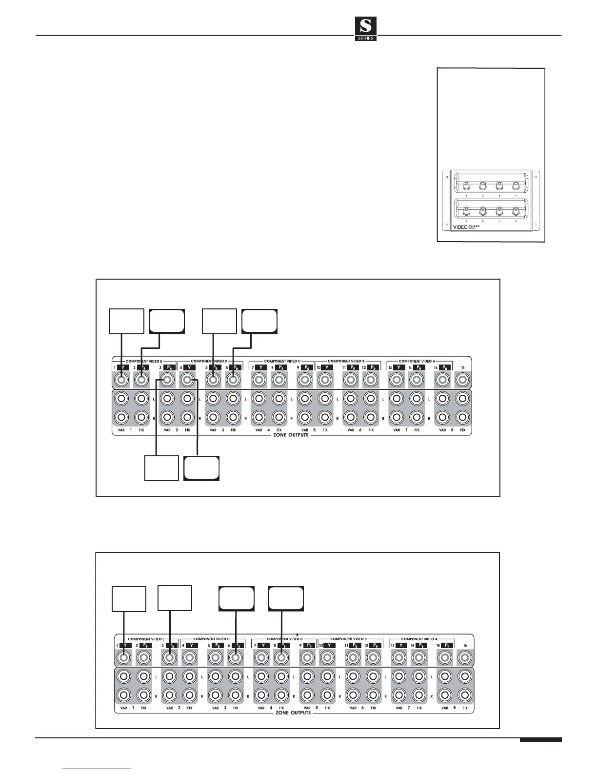
Video Zone Output Connections: Composite
Default Tracking Mode
In the Default Tracking Mode, there are two pre-configured video outputs for each
zone. The first output is configured for a VIA! Touch Panel, the second output for
a TV/monitor. When a video source is selected in a zone, both of these video out-
puts will automatically route the selected source video to that zone. The audio will
also be automatically routed to the zone.
The default Composite video zone outputs are:
• Zone 1: Video Outputs 1 - 2 • Zone 5: Video Outputs 9 - 10
• Zone 2: Video Outputs 3 - 4 • Zone 6: Video Outputs 11 - 12
• Zone 3: Video Outputs 5 - 6 • Zone 7: Video Outputs 13 - 14
• Zone 4: Video Outputs 7 - 8 • Zone 8: Video Outputs 15 - 16
As shown in the diagram below, not every zone will have both a VIA! Touch Panel
and a TV/monitor, therefore both Zone Video Outputs may not always be used.