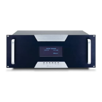
ELAN HOME SYSTEMS
SYSTEM12 INSTALLATION MANUAL
Page 20 © ELAN Home Systems 2004 • All rights reserved.
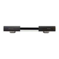
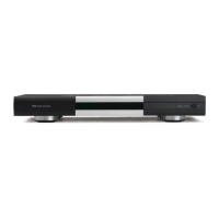
PS12 Precision Panel
TO SENSE INPUTS
Connects to SENSE TRIGGER INPUTS of the S12.
Enables automated functionality using Triggers/Sensors.
EXT IR IN
Connects to EXT IR IN of the S12. Control system sources
from areas that are not part of a Zone.
ZONE RJ-45 Jack
Connects to ZONE KEYPAD INPUTS of the S12 using ELAN C4545
1 or 2 meter RJ-45 interconnect cables. Main portals for IR Zone
Control from keypads, VIA!s, and IR receivers.
LOCAL RJ-45 Jack
Connect to LOCAL SOURCE INPUTS of S12 using ELAN C4545
1 or 2 meter RJ-45 interconnect cables. Allows connection of
8 remote sources.
VIA! POWER
• 16VDC/10A
Connect an ELAN 16 VDC/10A power supply for powering
up to 10 VIA!s.
• 16VDC/4A
Connect an ELAN 16 VDC/4A Power Supply for powering
up to 4 VIA!s.
EXT IR IN
Cat-5 connections from non-system IR receivers
VIA! Punch-Down Connectors
Cat-5 connections from VIA! Touch Panels
KP Punch-Down Connectors
Cat-5 connections from ELAN keypads or IR receivers
LS Punch-Down Connectors
Cat-5 connections from the Local Source Wall Plate (LSWP)
LINK IN RJ-45 Jack
Cat-5 connections from another PS12 when using multiple PS12s
LINK OUT RJ-45 Jack
Cat-5 connections to another PS12 when using multiple PS12s
SENSE
Cat-5 connections from ELAN™Sense Sensors
V+ G
Connect external power wires for VIA! Touch Panels
on runs longer than 110 feet
ADDITIONAL IR INPUTS
VSE IR connections from PVSE Precision Panel
Front Panel
Rear Panel
SS/SC4 Switch
Flip switch Up when using VIA!2 SS1 System Station
or VIA! SC4 System Controller
Or
Bl
GSG
V
GS
V
G
SENSE 3
V
SENSE 4
V
GSGSGG
SENSE 6
GS
SENSE 5
GS
V
GG
V
LS3 VIA3 LS2KP3 VIA2 LS1KP2 VIA1 KP1
W/Or
W/Br
W/Gr
Br
Gr
W/Bl
Or
Bl
LS5
VIA5
LS4
KP5 VIA4 KP4
LS6
VIA6 KP6
VIA8
LS7
VIA7 KP7
G
16V
16V
G
485+
485-
IR
SN
Gr
Br
W/Br
W/Gr
Bl
Or
W/Or
W/Bl
SS/SC4
NO SS/SC4
IR
ADDITIONAL IR INPUTS
6
5
IR
G
IR
G
IR
G
7
G
8
LINK OUT
BLACK -
RED +-
Gr
Br
W/Br
W/Gr
Bl
Or
W/Or
W/Bl
FM ANTENNA XM
V+
nc
6
V+
G
G
7
G
8
V+ V+
910
V+
G
5
V+
nc
G
V+
1
V+
G
2
G
3
V+ V+
4
G
ADDITIONAL IR INPUTS
IRIR
G
1
IR
G
2
G
3
IR
G
4
LINK IN
LS8
KP8
SENSE 1SENSE 2
EXT IR
G
IR
G
IR
G
IR
G
IR
IR+
L-
L+
V+
R+
R-
G
IR-
IRIR
485+
485-
+12V
GG
16V
nc
16V
G
485+
485-
nc
SN
nc
IR
IR+
L- G
L+
16V
V+
R+
R-
G
16V
G
485+
485-
IR-
SN
IR
nc
485+
nc
G
+12V
nc
485-
IR+
L-
L+
R+
R-
G
V+
IR-
IR
485+
nc
nc
G
nc
+12V
485-
IR
G
16V
16V
G
485-
485+
SN
nc
nc
G
485-
+12V
nc
485+
IR
SN
G
16V
G
16V
485-
485+
IR
IR+
G
R-
R+
L-
IR-
L+
nc
nc
G
+12V
485-
IR
485+
nc
V+
SN
IR-
G
R-
16V
16V
L+
L-
R+
G
485-
485+
G
V+
IR+
IR
SN
nc
+12V
nc
IR
485+
485-
G
nc
G
16V
G
16V
485-
485+
IR
IR-
R-
L-
L+
R+
G
V+
IR+
Bl
Gr
Br
W/Gr
W/Br
Or
W/Bl
W/Or
R+
L+
L-
G
V+
R-
IR-
IR+
IR
nc
+12V
485+
485-
nc
nc
16V
G
16V
G
485+
485-
IR
SN
W/Or
Gr
Br
W/Gr
W/Br
Or
W/Bl
Bl
W/Or
W/Br
W/Gr
Br
Gr
W/Bl
ANTENNA
• XM Connect to ELAN's XM3 Satellite Radio Tuner.
• FM Connect to ELAN's DTNR Digital Dual Tuner or other FM Tuner.
VIA!NET RJ-45 Jack
Connect to a VIA!SC4 Serial Controller or VIA!SS1 using ELAN
C4545 1 or 2 meter RJ-45 interconnect cables. Allows for RS-232
control of the S12.
XM FM
12
3
4
56
+
--
1
ZONE
1
LOCAL
22
ZONE LOCAL
33
ZONE LOCAL
4
ZONE
4
LOCAL
55
ZONE LOCAL
6
ZONE
6
LOCAL
8
LOCAL
8
ZONE
7
LOCAL
7
ZONE VIA!POWER
16VDC / 10A
16VDC / 4A
VIA!NET
TO SENSE INPUTS
USE STEREO 3.5mm PLUGS ONLY
EXT IR
ANTENNA