ELAN HOME SYSTEMS
© ELAN Home Systems 2004 • All rights reserved. Page 49
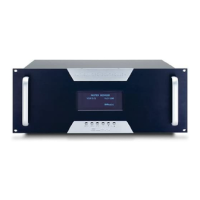
SYSTEM12 INSTALLATION MANUAL
Video Switching (continued)
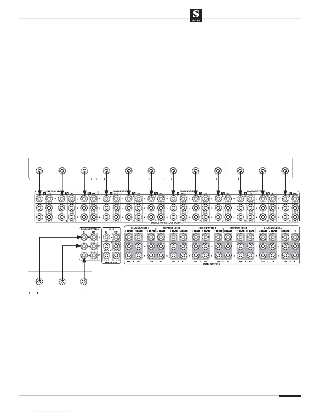
Component Video Switching
Component (Y, P
B
, P
R
) video signals can easily be
switched by the S12. Each Component video source
utilizes three video inputs; one for Y, one for P
B
, and
one for P
R
(Green, Blue, and Red). These inputs are
grouped together through programming to switch as
one entity.
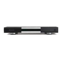
Component inputs are designated on the rear panel of
the S12 in reverse order.
These groups are labeled:
• A: Inputs 13, 14, 15
• B: Inputs 10, 11, 12
• C: Inputs 7, 8, 9
• D: Inputs 5, 5, 6
• E: Inputs 1, 2, 3
Use high quality Component video cables to connect
Component sources to the S12 as shown below.
Make sure to connect the proper Component cable to
the proper video input jack (Y, P
B
, P
R
).
Component Video Source Connections
Y
P
R
P
B
COMPONENT VIDEO OUTPUTS
Y
P
R
P
B
COMPONENT VIDEO OUTPUTS
Y
P
R
P
B
COMPONENT VIDEO OUTPUTS
Y
P
R
P
B
COMPONENT VIDEO OUTPUTS
Y
P
R
P
B
COMPONENT VIDEO OUTPUTS
1st Component video source
to Component video input ‘A’
(inputs 13, 14, 15)
S12
2nd Component video source
to Component video input ‘B’
(inputs 10, 11, 12)
3rd Component video source
to Component video input ‘C’
(inputs 7, 8, 9)
4th Component video source
to Component video input ‘D’
(inputs 4, 5, 6)
5th Component video source
to Component video input ‘E’
(inputs 1, 2, 3)