ELAN HOME SYSTEMS
© ELAN Home Systems 2004 • All rights reserved. Page 75
5. Troubleshooting
Diagnostics Menu
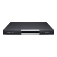
The S12 features a Diagnostics Menu that is designed
to provide easy access to S12 system status and
current programming. All diagnostics information is
displayed on the S12’s front panel. Menus exist for
Firmware Version, Video Inputs and Outputs, Sense
Inputs, Groups, and Factory Default. The pages with-
in the Diagnostics Menu provide a map of the S12’s
configuration and are invaluable when trouble-shoot-
ing.
Firmware Version Screen
To access the Diagnostics Menu, press and hold the
DND button for 2.5 seconds. The first screen will
appear and provide the Firmware revision
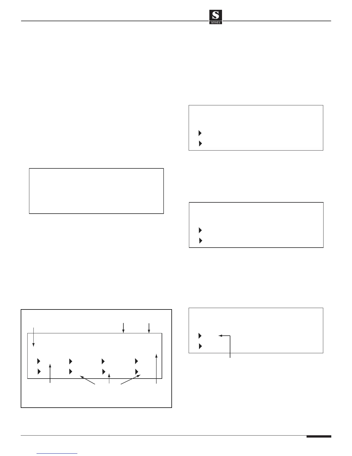
Video Screen
Press DND again to cycle to the next screen which
will display programmed video information. The
example screen below shows (for Source 1, Zone 1)
that Outputs 1, 2, 3, and 4 are assigned to VIA!
®
Touch
Panels in Zone 1 (the numbers on the second line
“1 2 3 4” designate that touch panels are connected).
Output 5 is assigned to a monitor in Zone 1 (monitors
are represented by “5”) and Outputs 14, 15, and 16
are Component video outputs also assigned to Zone
1 (designated by “Y, B, R”).
The next example screen shows Zone 1 with Source 3
selected. Output 1 goes to a VIA! Touch Panel (1),
Output 2 goes to a monitor (5). The touch panel con-
nected to Output 1 is displaying Input 3, the monitor
connected to Output 2 is displaying Input 3, as well.
The example screen shown below shows Zone 1 with
Source 4 selected. Output 1 goes to a VIA! Touch
Panel, Output 2 goes to a monitor. The touch panel
connected to Output 1 is displaying Input 4, the
monitor connected to Output 2 is displaying Input 4.
The last example shows Zone 1 with Source 3 select-
ed and a camera selected. The touch panel (1) on
Output 1 is displaying the camera connected to Input
16, while the monitor connected to Output 2 (5) is dis-
playing Input 3. The * indicates that the output is not
tracking with the audio source selected.
Note: This display is only valid for Default
Tracking Mode and Source-Select Tracking Mode.
It is invalid for 16 X 16 Mode.