© ELAN Home Systems 2004 • All rights reserved. Page 31
VIA!
®
Touch Panel Connections
If not using the PS12, it is necessary to use a PVIA
Wall Plate when connecting VIA! Touch Panels to the
S12. VIA! Touch Panels require the 16V power sup-
plies that are included with each PVIA wall plate
(PVIA1, PVIA4, and PVIA10).
ELAN Precision Panels save
time and make sense out
of complex wiring jobs!
XM FM
12
3
4
5 6 MONO
+
--
1
ZONE
1
LOCAL
22
ZONE LOCAL
33
ZONE LOCAL
4
ZONE
4
LOCAL
55
ZONE LOCAL
6
ZONE
6
LOCAL
8
LOCAL
8
ZONE
7
LOCAL
7
ZONE VIA!POWER
16VDC / 10A
16VDC / 4A
VIA!NET
TO SENSE INPUTS
USE STEREO 3.5mm PLUGS ONLY
EXTIR ANTENNA
BLUE
WHITE/BLUE
ORANGE
WHITE/ORANGE
GREEN
WHITE/GREEN
BROWN
WHITE/BROWN
1
2
3
4
5
6
7
8
PIN # COLOR CODE
FRONT
CABLE
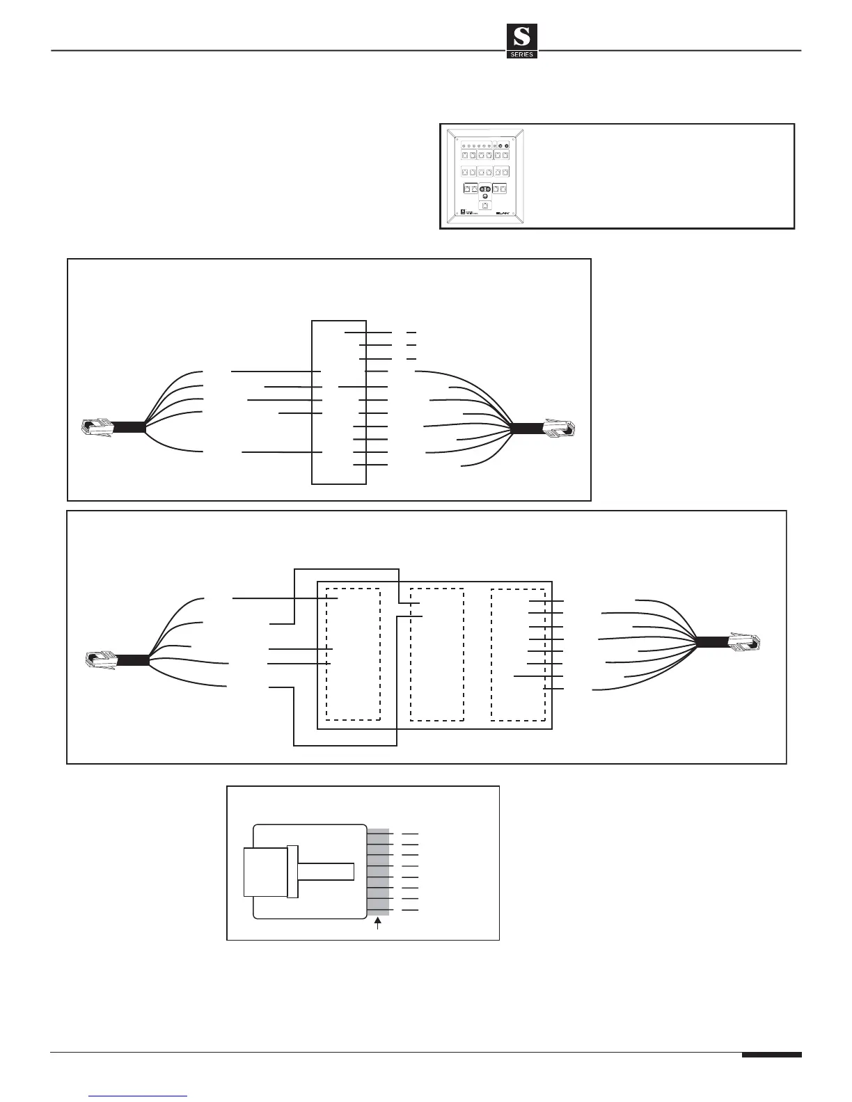
Standard ELAN RJ-45 Pin-Out
TAB
S12 to PVIA1 (No PS12)
ELAN
C45P
To VIA!
Touch
Panel
PVIA1
GND
+16V
GND
SIR
Z485-
Z485+
ST/SNS
IR
V485-
V485+
+16V
White/Blue
Green
White/Orange
Brown
White/Blue
Orange
White/Orange
Green
White/Green
Brown
White/Brown
nc
nc
nc
ELAN
C45P
S12 to PVIA4/PVIA10 (No PS12)
ELAN
C45P
To VIA!
Touch
Panel
GND
+16V
GND
ST/SNS
IR
485-
485+
+16V
Green
White/Orange
Brown
White/Blue
Orange
White/Orange
Green
White/Green
Brown
White/Brown
ELAN
C45P
VIA1
IR
XLINK
Z485-
Z485+
IR1
GND
ST1
ST2
ST3
ST4
SIR
GND
IR2
GND
IR3
GND
IR4
GND
White/Blue
To S12
PVIA4/PVIA10
Blue
Blue
Blue
Blue
S12 Connections When NOT Using a PS12 Precision Panel
SYSTEM12 INSTALLATION MANUAL