ELAN HOME SYSTEMS
SYSTEM12 INSTALLATION MANUAL
Page 22 © ELAN Home Systems 2004 • All rights reserved.
PS12 Rear Panel Connections (continued)
Keypad Connections
Keypads will punch-down to the rear of the PS12 at the Keypad punch-down
locations. These locations are labelled KP1, KP2, etc. corresponding to the
zone that the keypad(s) will control. Two keypads can connect to the PS12’s
rear panel for each zone. If using more than 2 keypads per zone, make connec-
tions off of the PS12 and use jumper wires to punch-down to the correct location.
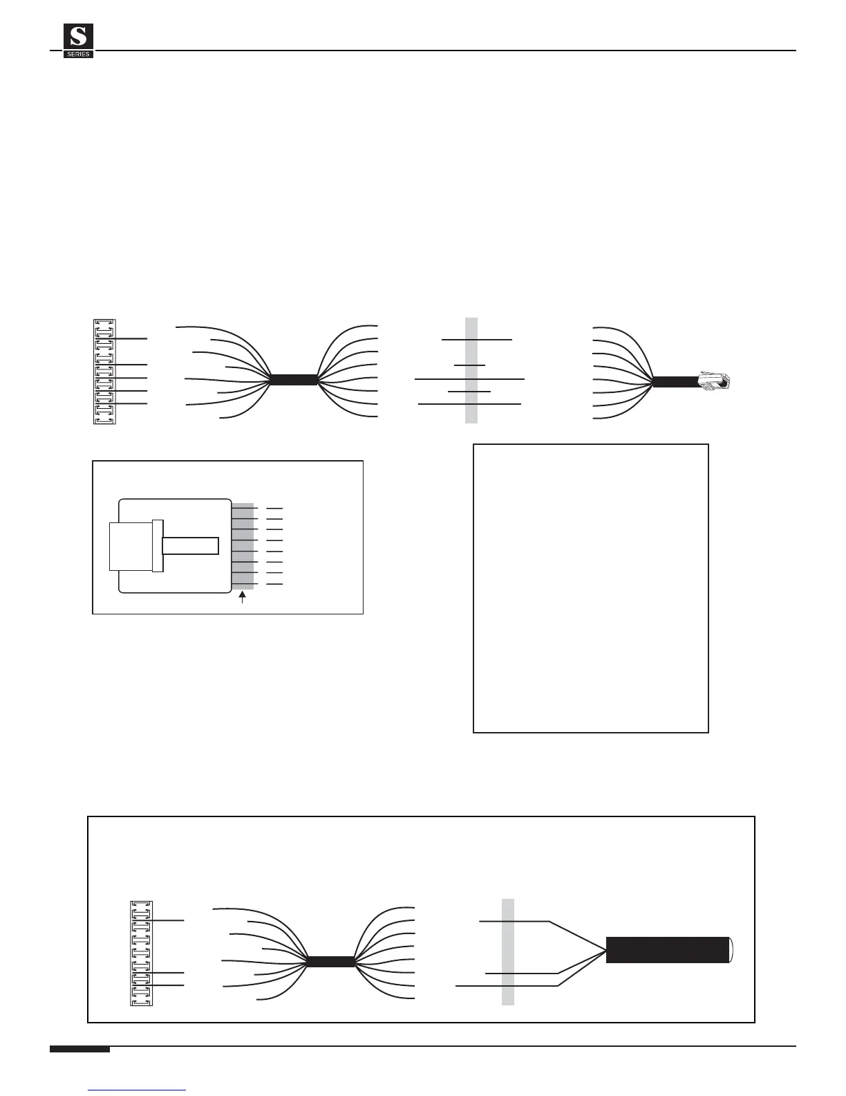
The diagram below shows the correct wiring for one keypad in one zone.
Cat-5
PS12 Precision Panel
Keypad (KP)
Connector
Blue
White/Blue
Orange
White/Orange
Green
White/Green
Brown
White/Brown
nc
IR
nc
485+
485-
+12V
GND
nc
ELAN
C45P
Butt splice
or equivalent
Blue
White/Blue
Orange
White/Orange
Green
White/Green
Brown
White/Brown
Blue
White/Blue (IR)
Orange
White/Orange (485+)
Green (485-)
White/Green (+12V)
Brown (GND)
White/Brown
ELAN
Keypad
BLUE
WHITE/BLUE
ORANGE
WHITE/ORANGE
GREEN
WHITE/GREEN
BROWN
WHITE/BROWN
1
2
3
4
5
6
7
8
PIN # COLOR CODE
FRONT
CABLE
Standard ELAN RJ-45 Pin-Out
TAB
PS12 To Keypad Connections
IMPORTANT NOTE
Keypads, VSEs, & IR
Each ZONE KEYPAD INPUT
RJ45 jack on the S12 provides
12VDC 300mA.
You may choose to load each of the
S12’s ZONE KEYPAD INPUTS
with any combination of ZPADs,
IR Receivers, or Electronic
Volume Controls as long as
the total current consumption
DOES NOT EXCEED 300mA.
Keypad w/IR Tube = 65mA
Z025 = 85mA
Electronic Volume Control = 40mA
Additional IR Receivers = 10mA
IR Receiver Connections
Stand-alone IR receivers can easily connect to the PS12 KP punch-downs.
Connect +12V, IR, and GND to the specific zone that is to be controlled.
Cat-5
PS12 Precision Panel
Keypad (KP)
Connector
Blue
White/Blue
Orange
White/Orange
Green
White/Green
Brown
White/Brown
nc
IR
nc
485+
485-
+12V
GND
nc
Butt splice
or equivalent
Blue
White/Blue
Orange
White/Orange
Green
White/Green
Brown
White/Brown
PS12 to IR Receiver Connections
IR Receiver
IR
+12 VDC
GND