Vv CM78N_C02_1.ING.doc 28/05/2009 page 5/6
OPERATIONAL MODE 1
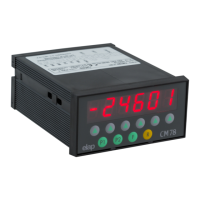
POSITION VISUALISER WITH TWO SETTABLE THRESHOLDS
FUNCTIONS
Multiplying factor
Count load
mm/inch conversion
Display/count block
2 alarm outputs
OPERATING MODE
MAIN DISPLAY PAGE
The display shows the value of the count record multiplied by the
set factor. Positive numbers are shown without sign indication,
while negative numbers are precedeed by the minus sign; values
exceeding -99999 are displayed without – sign, with the first digit
flashing.
ALARM THRESHOLDS
Two alarm thresholds, called positive and negative stroke ends,
can be set; they are enabled by comparison, respectively for ≥
and ≤ value than the count record.
VALUE SETTING BY KEYBOARD
During the setting phase of a numerical value a dot flashes on the
right display side.
The key R sets the value to 0.
The Arrow keys modify the value.
The minus sign is obtained by pressing the Arrow key 1 until
exceeding number 9. The max negative set is –99999.
SETTING THE POSITIVE STROKE END VALUE (free setting)
The phase is accessed by pressing the key P1: the display shows
FC POS followed by the current value.
Modify the value with the Arrow keys, then press P1 again to
store the new value and switch back to the main display page.
The set value is compared for ≥ with the count record value to
enable or disable output 1.
SETTING THE NEGATIVE STROKE END VALUE (free setting)
The phase is accessed by pressing the key P2: the display shows
FC NEG followed by the current value.
Modify the value with the Arrow keys, then press P2 again to
store the new value and switch back to the main display page.
The set value is compared for ≤ with the count record value to
enable or disable output 2.
SETTING THE LOAD VALUE (free setting)
The phase is accessed by pressing the key R: the display shows
LoAd followed by the current value. Modify the value with the
Arrow keys, then press F to store the new value and switch back
to the main display page.
LOADING THE VALUE
LOADING by input is always enabled.
LOADING by KEYBOARD can be enabled, and can operate in
two different ways, depending whether the load setting is free or r
under key.
Free setting: after confirming the LOAD value (key F) the display
shows the flashing message LoAd. The key R loads the value,
any other key cancels the operation.
Setting under key: pressing the key R the
display shows the
flashing message LoAd. Pressing R again the value is loaded,
any other key cancels the operation.
INPUTS
The instrument is equipped with three inputs performing the
following operations:
IN1 = load
IN2 = mm/inch display switch
IN3 = count block or visualisation block
IN1: LOAD BY INPUT
Closing input IN1 the LOAD value is displayed.
If the function ‘load on the closure state’ was selected, the pulses
count is blocked until input IN1 is opened again.
IN2: mm/inch CONVERSION
Closing inpunt IN2 the display indication is switched form mm to
inch. The ‘inch’ displayed value has one decimal digit more than
the ones set for the ‘mm’ value.
The set LOAD and STROKE ENDS values are also converted
automatically.
IN3: VISUALISATION/COUNT BLOCK
If the count block function was selected, the pulses count is
stopped by closing input IN3.
If the visualisation block function was selected, the display update
of the pulses count is suspended when closing input IN3.
The input pulses count goes on and the updated value is
displayed when input IN3 is opened again.
OUTPUTS
The instrument is equipped with 2 alarm signal outputs.
OUT 1 = Positive stroke end
OUT 2 = Negative stroke end
PARAMETERS SETTING
Press the key F and, when the display shows Ch.Set, digit the
key sequence P2 F P1 within 5 seconds to access the
parameters setting phase.
During the setting phase of a numerical value a dot flashes on the
right display side.
The key R sets the value to 0.
The Arrow keys modify the value.
The minus sign is obtained by pressing the Arrow key 1 until
exceeding number 9. The max negative set is –99999.
Press F to confirm the set value and switch to the following
parameter.
PARAMETERS LIST
Load (setting under constants key)
The display shows LoAd followed by the current value.
The LOAD value is stored into the count record by closing input
IN1.
Output 1 Excitation Time (for selection: timed pulse outputs)
T
he display shows tout 1 followed by the current value of output
1 excitation time expressed in seconds.
Default value 0.3 S.
Mimimum setting 0.1 S, max setting 25.0 S.
Output 2 Excitation Time (for selection: timed pulse outputs)
The display shows tout 2 followed by the current value of output
2 excitation time expressed in seconds.
Default value 0.3 S.
Mimimum setting 0.1 S, max setting 25.0 S.
Stroke ends (setting under constants key)
The display shows FC POS. followed by the current value.
The value is compared with the count record value to enable or
disable output 1.
After confirming the positive end stroke value the display shows
FC nEg. followed by the current value.
The value is compared with the count record value to enable or
disable output 2.
Multiplying Factor of the Count Pulses
The display shows FAtt. followed by the current value of the
multiplying factor of the input pulses. The value can range
between 0.01 and 9.99999.
After confiming the value the display is switched back to the main
display page.
 Loading...