Do you have a question about the Elation SIXPAR 300 and is the answer not in the manual?
Please read and understand the instructions in this manual carefully and thoroughly before attempting to operate this device.
Carefully check the shipping carton for damage that may have occurred during shipping. Inspect device for damage.
List of items included with the fixture: power cable, DMX cables, manual & warranty card.
Contact ELATION Service for any product related service and support needs.
Elation Professional warrants products to the original purchaser for two years against manufacturing defects.
Service requires factory shipment, pre-paid. No accessories should be sent with the product.
Warranty void if serial numbers altered, product modified, or unauthorized service.
Covers parts replacement, not maintenance. Limits implied warranties and liability.
Returned items must have a clearly marked R.A. number on the package.
Fixture must be properly grounded as it is a Protection Class 1 device.
Do not attempt repairs yourself; doing so voids warranty and can cause damage.
Do not plug into dimmer pack, never open while in use, unplug before servicing, keep away from flammables.
Never look directly into the light source; retina injury risk may induce blindness or epileptic shock.
Maintain 65.6ft to objects, 1.6ft to flammables. Max surface temp 212°F.
Risk Group 3 UV exposure. Wear eye/skin protection, avoid prolonged exposure, avoid direct exposure under 11 feet.
Do not touch housing during operation, unplug before servicing, do not shake, check power cord.
Do not block air ventilation slots. Ensure 6" (15cm) clearance for proper cooling.
A light smoke or smell may emit during initial operation due to excess paint burning off.
Consistent operational breaks ensure longevity. Use original packaging for transport.
Features MODE, UP, DOWN, ENTER buttons for system menu navigation and adjustments.
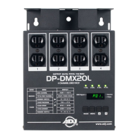
Includes POWER IN, FUSE, POWER OUT, DMX IN/OUT (3-pin and 5-pin).
Includes 'S' Knobs and Mounting Brackets/Yokes for securing the fixture.
Features a lens array for light output.
Keep fixture minimum 5.0 feet (1.5m) away from flammables. Maintain 1.6ft to objects.
Use a qualified electrician. Do not install if unqualified.
Caution with power linking. Max ambient temp 113°F (45°C).
Requires experience, follow codes, use safety attachments, never stand below.
Operate within 14°-113°F. Allow 10 min to cool before serving.
Secure clamp to yokes using M10 screw. Use designated rigging points for safety cables.
ALWAYS attach safety cable when installing in suspended environment to prevent falls if clamp fails.
Overhead rigging requires experience. Improper installation can result in bodily injury.
DMX is a universal protocol for communication between lighting fixtures and controllers.
Use IP rated DMX cables, shortest path possible. Never split a DMX line with a 'Y' connector.
Requires standard 3-pin or 5-pin XLR connectors for data input/output. Lines must be daisy-chained.
Connect controller's female XLR output to fixture's male XLR input. Multiple fixtures can be chained.
Use a 120 ohm terminator on the last fixture in the DMX line to avoid erratic behavior.
Set a DMX starting address to ensure correct control signal. Address is the channel number the fixture listens to.
Same address controls all fixtures together. Different addresses control individual fixtures.
Check cable connection, controller status, cable integrity, and terminator presence if no DMX signal is received.
RDM is a protocol on top of DMX for remote modification and monitoring of fixtures.
Ideal for units in hard-to-access locations, allowing bi-directional control (GET/SET commands).
Parameters like DMX Address, Channel Mode, and Temperature Sensors are accessible via RDM.
Not all RDM devices support all features; check compatibility before use.
The fixture has an easy-to-navigate system menu for adjustments.
Features MODE, UP, DOWN, ENTER buttons for system menu navigation and adjustments.
Use MODE to navigate, ENTER to select, UP/DOWN to adjust values. Press MODE to exit.
Displays 'Update Wait...', 'SIXPAR 300', and '300 V1.14' (Software Version).
Panel can be locked after 30s if Display ON is OFF1. Unlock sequence involves pressing UP/DOWN buttons.
Covers Channel, DMX Mode, Secondary Mode, Display On/Off settings.
Includes MANUAL color adjustment, CHANGE (Color Chase Macro), and FADE (Color Fade Macro) programs.
Options for Standard, Stage, TV, Architectural, Theatre dimming curves.
Blackout, Hold, and Fade options for when no DMX signal is present.
Illustrates dimmer output over time, showing Rise Time and Down Time.
Shows 0 sec and 1 sec fade times with corresponding Rise and Down Times for different curves.
Displays Linear, Square, Inverse Square, and S-Curve dimming profiles.
Channels 1-6 control Red, Green, Blue, White, Amber, and UV intensity (0-255).
Channel 7 controls the overall dimmer intensity (0-255).
Channel 8 controls LED OFF, Strobe Effect (Slow to Fast), and Random Strobe Effect.
Channels 9 provides access to various color macros, from RED to RED+GREEN+BLUE+WHITE+AMBER+UV.
Continues listing color macros for combined colors up to RED+GREEN+BLUE+WHITE+AMBER+UV.
Channel 10 controls Color Chase and Color Fade Chase effects, with 'No Function' options.
Channel 11 controls the speed of Color Chase macros from Slow to Fast.
Channel 12 selects dimming modes: Standard, Stage, TV, Architectural, Theatre.
Clean optics with a soft cloth every 20 days. Never use alcohol, solvents, or ammonia cleaners.
Regular inspections ensure proper function. Refer service issues to authorized technicians.
Detailed electric check by engineer every three months for circuit contacts and to prevent overheating.
Ensure all screws and fasteners are securely tightened to prevent parts falling.
Power supply cables must not show damage, material fatigue or sediments. Never remove ground prong.
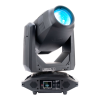
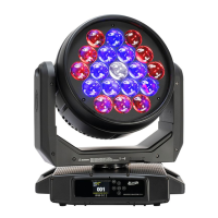
Features (18) 12W 6-in-1 RGBAW+UV LEDs with 100,000 Hour Average LED Life.
Provides LUX and FC values at various distances and beam angles (15° Full ON).
Includes Electronic Strobe, Color/Chase Macros, Electronic Dimming (0%-100%), and 5 Dimming Curve Modes.
4 DMX modes, 4-button control panel, LCD display, 3/5pin DMX, Twist Locking Power Cable.
Length: 14.4″, Width: 4.9″, Vertical Height: 14.4″. Weight: 18.0 lbs (8.1 kg).
AC 110-250V, 220W max power. Operating temp: 5°F to 113°F (-15°C to 45°C). UV Wavelength: 395nm.
CE, CETLus, IP65 certified by ETL Intertek.
Includes power cable, 3-pin DMX cable, 5-pin DMX cable.
Current Version: V1.14. Link provided for software updates.
Table showing beam diameter and field diameter at various distances and angles.
Details LUX and FC for Red, Green, Blue, White, Amber, UV LEDs and Full ON at different distances.
Diagram showing the fixture's physical dimensions in inches and millimeters.
Lists order codes and corresponding items like Gel Frame Holder, Barn Door, and Clamps.
Includes various light shaping filters with different beam angles (30°, 20°, 60°, 10°).
Offers Wireless DMX System, transmitters, receivers, and various DMX/power cables.
Device complies with Part 15 of FCC Rules, subject to two conditions to avoid harmful interference.
Provides guidance on preventing and correcting harmful interference to radio/TV reception.
Advises turning off electrical products when not in use to save energy and protect the environment.
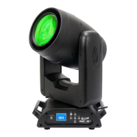
The Elation SIXPAR 300™ is a sophisticated electronic lighting fixture designed for professional use, offering a range of features for versatile lighting applications. This device is controlled via DMX-512 protocol, allowing for integration into complex lighting systems and remote management.
The SIXPAR 300™ functions primarily as a DMX-controlled lighting fixture, capable of producing a wide spectrum of colors and effects. It features (18) 12W 6-in-1 RGBAW+UV LEDs, enabling it to generate red, green, blue, amber, white, and ultraviolet light. This broad color palette allows for extensive creative control over lighting environments. The fixture supports multiple DMX channel modes (6, 7, 8, or 12 channels), providing flexibility in how it is controlled by a DMX controller.
A key function of the SIXPAR 300™ is its ability to operate within a DMX-512 network, which is a universal protocol for communication between intelligent fixtures and controllers. This allows multiple SIXPAR 300™ units, or other DMX-compliant devices, to be linked together and controlled from a single DMX controller. The fixture sends and receives DMX data via standard 3-pin or 5-pin XLR connectors, facilitating daisy-chaining in a DMX line.
The device also incorporates Remote Device Management (RDM) capabilities. RDM is a protocol that sits atop DMX512, enabling bi-directional communication between the fixture and an RDM-enabled controller. This allows for remote modification and monitoring of fixture settings, such as DMX address, DMX channel mode, and temperature sensors. This feature is particularly useful for fixtures installed in hard-to-reach locations, as it eliminates the need for direct physical access to adjust settings.
Beyond DMX control, the SIXPAR 300™ offers internal programs for standalone operation or simplified control. These include color chase macros (30 Color Chase Macro, 6 Color Chase Macro) and a color fade macro, each with adjustable speed and strobe effects. The fixture also provides various dimming curve modes (Standard, Stage, TV, Architectural, Theatre) to suit different application requirements, ensuring smooth and precise dimming from 0% to 100%. An electronic strobe effect is also built-in, offering various strobe speeds and patterns, including pulse and random strobe effects.
The SIXPAR 300™ is designed for ease of use and installation, with several features enhancing its operational flexibility. The fixture includes a 4-button touch control panel and an LCD menu display located on its back, providing an intuitive interface for accessing and adjusting settings. Users can navigate through different function menus using the MODE button, select menus with the ENTER button, and adjust variable fields with the UP and DOWN buttons. This on-board system menu allows for direct configuration of DMX address, channel modes, internal programs, and dimming curves.
For safety and security, the LCD control panel can be locked to prevent unauthorized changes. This lockout feature is activated after a specified period of inactivity and requires a specific sequence of button presses to unlock, ensuring that settings remain as configured.
Installation is facilitated by dual yokes, which serve as rigging points for mounting the fixture to a truss using an appropriately rated professional-grade rigging clamp (not included). The yokes also provide a designated point for attaching a secondary safety cable, which is crucial for suspended installations to prevent the fixture from falling if the primary clamp fails. The fixture's "S" knobs allow for tightening the brackets/yokes, ensuring secure positioning.
The SIXPAR 300™ is equipped with twist-locking power cables for secure power connections and supports multiple unit power linking, simplifying power distribution in multi-fixture setups. It also features 3-pin and 5-pin DMX input and output connectors, offering compatibility with various DMX systems. For optimal DMX data transmission, especially in longer runs, the use of a DMX terminator is recommended, and the manual provides guidance on its connection.
The fixture's robust design and IP65 rating indicate its suitability for outdoor use and protection against dust and water ingress, expanding its application possibilities to environments where weather resistance is required.
Maintaining the SIXPAR 300™ is straightforward, focusing on routine cleaning and inspections to ensure optimal performance and extended lifespan. The manual emphasizes the importance of frequent cleaning, especially in damp, smoky, or dirty environments, to prevent dirt and debris accumulation on the fixture's optics. Cleaning the external lens surface every 20 days with a soft cloth is recommended, while explicitly advising against the use of alcohol, solvents, or ammonia-based cleaners.
For safety, it is crucial to disconnect power before performing any maintenance or cleaning procedures. The fixture is designed with no user-serviceable parts inside, meaning all service issues should be referred to an authorized Elation service technician. This approach ensures that any repairs or part replacements are handled by qualified personnel, preserving the manufacturer's warranty and the fixture's integrity.
Regular inspections are a key aspect of maintenance, recommended to ensure proper function and extended life. These inspections should include:
The fixture also requires adequate cooling space, with a recommendation to allow approximately 6 inches (15cm) between the fixture and other devices or walls. All fan and air inlets must remain clean and unobstructed to ensure proper ventilation and prevent overheating. After operation, it is advised to turn off the power and allow approximately 15 minutes for the fixture to cool down before handling or servicing.
For transportation, especially for service, it is recommended to use the original packaging and materials to protect the fixture. These maintenance guidelines are designed to ensure the SIXPAR 300™ operates reliably and safely over many years.
| Input/Output | 3-pin XLR |
|---|---|
| Voltage | 100-240V AC, 50/60Hz |
| IP Rating | IP20 |
| Type | Par Can |
| Beam Angle | 25 degrees |
| Field Angle | 40 degrees |
| Control | DMX |
| Operating Modes | Master/Slave |