2
1
5
4
3
7
6
8
JP3
V
W
+
-
R
a b
1 2
ON
AN_BVM-100_EN_110131
Video intercom BVM-100
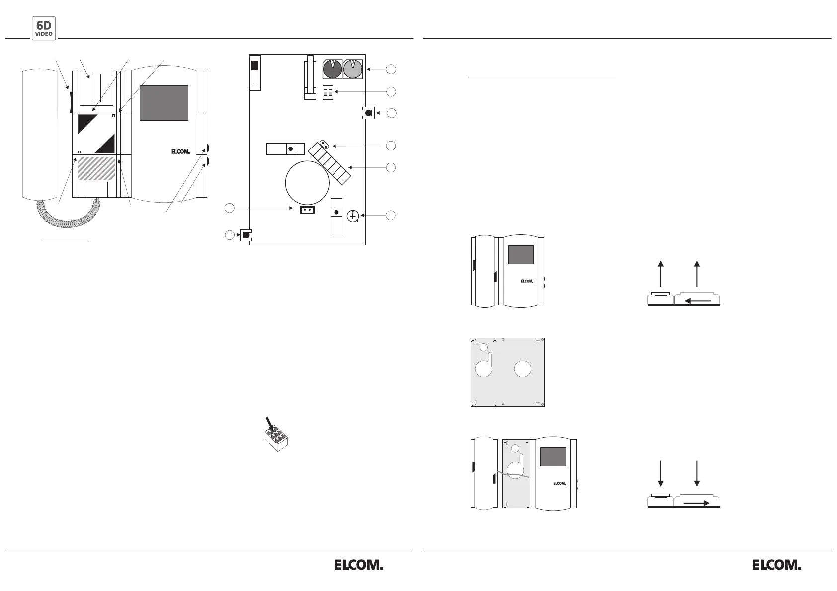
Description:
1.Rotary coding switch for address configuration
Black: Group address 0-F (Setting of the corresponding BTE-116)
Blue: Intercom address 0-F (Terminal of the corresponding doorbell button on BTE-116)
NOTE: A maximum of 3 intercoms with the same address can be installed (parallel operation).
2.Operating Mode Switches
Switch 1: OFF = Light (I/O button) and door opener (TÖ button) at all times (Factory setting)
ON = Internal call to address "F/F” (IO button) and "F/E” (TÖ button).
Switch 2: OFF = No storey call forwarding (factory setting)
ON = Storey call forwarding to intercoms with the same address
3.Green LED
Off: Basic condition – Dial tone can be heard when handset is lifted.
Blinking: Communication ready – Communication ready for 90 seconds after ringing.
On: Speech mode – Automatic shut off after 3 minutes of door communication.
4. Video cable terminator (100 Ohm)
The jumper (JP3) must be pushed in at the last intercom of the video line
and pulled out on all prior intercoms!
5. Terminal clamps
Terminal a/b: ELCOM i2-BUS
Terminal R: Floor call button (opposite pole to terminal a or b)
Terminal +/-: Power supply (15V DC)
Terminal V/W: Symmetric video signal (1Vp-p Z=100Ohm)
6. Video quality / Cable compensation
7. Red LED
Off: Ring tone audible – call adjuster loud, medium or soft.
Blinking: Ring tone turned off – call adjuster in mute position (below)
8. Socket for control relay BSR-100
Set the ring tone
12 harmonic ring tones (6 of these are gong tones) are available which can be assigned to the different
door stations, the storey call or the internal call. The ring tone last used will always be preset. Lift the
handset and keep the hook switch pressed. Press the I/O button until you hear the desired ring tone.
Then release the hook switch and replace the handset.
Green LED
Door opener
button
Brightness
Contrast
Volume control
Red LED
I/O button
Hook switch
Connect the conductor:
Simply insert the conductor.
(Solid conductor 0.4 – 0.8 mm)
Loosen the conductor:
Press the orange button.
Remove the conductor.
Ø
Hotline: hotline@elcom.de
7. 5.
6.
1. 3.
2.
Oben
Oben
Art.Nr.: 0221107
Technical additions and printing errors do not constitute grounds for any claims to damages.
4. fixing the mounting plate.
Releasing telephone and monitor unit
from the mounting plate .
Fastening telephone and monitor unit
to the mounting plate .
Notes for video intercom assembly
The ELCOM Video intercom consists of the following units:
Phone, display and mounting plate.
1. take off the phone from the lower left corner of the mounting plate.
2. -3. slide the display to the left and lift apart.
4. fix the mounting plate.
5.-7. After fixing the mounting plate, reverse order of reassembling.
 Loading...