Do you have a question about the ELCOS CEM-256/10 and is the answer not in the manual?
Notifies users via SMS and allows pump start/stop control.
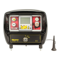
Offers status viewing, high-gain antenna, and flexible installation.
Utilizes electronic pressure switch and digital pressure gauge.
Displays hour-meter, oil pressure, temperature, tachometer, water pressure, fuel level.
Shows pump protection status, timer, and intervention alerts.
Displays battery/oil status and emergency stop indication.
Explains readings for pressure, speed, temperature, and fuel level.
Details functions of START, STOP, and adjustment buttons.
Describes OFF, AUT, and AVV modes for the start key.
Identifies common reasons for motor pump stoppage.
Controls system pressure, replacing the conventional pressure switch.
Allows low pressure adjustment; overpressure is fixed at 2 bar.
Explains activation, intervention, and exclusion of pump protection.
Sets motor pump work time up to 96 hours.
Details engine protections, indicator lights, and their delays.
Describes enabling, intervention, and exclusion of pump protection.
Lists conditions for stopping the motor pump, including key commands.
Explains how to view and interpret anomalies that cause pump stoppage.
Covers automatic restart via cell phone, startup failure, and general alarms.
Details how to select and view various instruments on the control unit.
Enables SMS alerts, phone number programming, status display, and remote control.
Instructions for inserting SIM card and disabling PIN code.
Guides on checking signal strength and antenna positioning.
Details wiring for coolant level probes for different radiator types.
Instructions for stopping the unit via solenoid valve or electromagnet.
Connects transmitters for thermometer and oil pressure gauge.
Wiring instructions for connecting the emergency stop button.
Guides on adjusting the tachometer for correct RPM display.
Details connections for emergency button, battery, and control unit.
Explains wiring for pre-excitation and permanent magnet alternators.
Lists optional accessories like electromagnets, pressure transmitters, and connectors.
Instructions for selecting the desired operating language.
Explains how SMS messages are sent to multiple users upon alarm activation.
Guides on programming cell phone numbers for SMS alerts.
Procedure to confirm reception of SMS warning messages.
Instructions for requesting and viewing motor pump status via SMS.
Commands to remotely switch off pump protection.
Commands to re-enable pump protection after it has been switched off.
Allows setting the motor pump running time via SMS command.
Commands to stop and restart the motor pump remotely.
Enables restarting the pump with pump protection switched off.
Advises on proper installation, wiring, and load compatibility.
Details safety measures for engine stationary, battery charging, and terminal disconnection.
Lists conditions where the control unit is not suitable for operation.
Information on CE marking standards and potential malfunctions.
Specifies weekly maintenance tasks for indicators, batteries, and terminals.
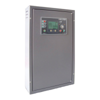
Provides physical dimensions and weight of the control unit.
Details battery voltage supply, circuit loading, and maximum current output.
Lists specifications for hour-meter, gauges, and transmitters.
Specifies environmental and protection ratings for installation.
Provides ordering codes for the control unit and available accessories.
| Manufacturer | ELCOS |
|---|---|
| Model | CEM-256/10 |
| Category | Control Panel |
| Number of zones | 256 |
| Number of outputs | 10 |
| Communication interface | RS485 |